
- 1【YOLOv5】手把手教你使用LabVIEW ONNX Runtime部署 TensorRT加速,实现YOLOv5实时物体识别(含源码)_labview调用yolo vt
- 2万字详文告诉你如何做 Code Review
- 3Python之赋值、深拷贝与浅拷贝_python赋值和浅拷贝
- 4小米开源文件管理器MiCodeFileExplorer-源码研究(2)-2个单实例工具类
- 5VSCode 的C++编译_vscode编译c++
- 6Spring整合SpringMVC的原理与实现_spring整合springmvc原理
- 7深度探讨 Golang 中并发发送 HTTP 请求的最佳技术_go的http.post的并发问题
- 8【conda】利用Conda创建虚拟环境,Pytorch各版本安装教程(Ubuntu)_ubuntu conda pytorch
- 9自动化测试岗实习3千5,转正1万8,技术在手真的太香了..._自动化专业去实习有工资么
- 10通过配置开关 Spring Boot 中的 @Scheduled 定时任务_scheduled定时任务增加个开关
NodeMCU ESP8266 基于Arduino IDE的串口使用详解(图文并茂)_nodemcu与arduion连用
赞
踩
NodeMCU ESP8266 的UART使用

前言
UART (Universal Asynchronous Receiver/Transmitter),串口通讯在嵌入式开发中至关重要,我们可以通过串口打印程序里的数据,也可以通过串口将数据发送到PC上并进行可视化的图形显示。
注意:相关的串口通讯的知识可以参考这篇文章
UART串口协议快速扫盲(图文并茂+超详细)
NodeMCU ESP8266开发板可以直接通过MicroUSB线和PC进行连接,在Arduino IDE内置的串口工具进行数据显示,下面我们进一步介绍。
硬件连接
基于 NodeMCU 的 ESP8266 有两个 UART 接口:UART0 和 UART1。
ESP8266通过UART接口的数据传输速度可以达到115200的40倍,即4.5Mbps。
默认情况下,对于 40MHz 振荡器,UART0 波特率为 115200。
可以根据应用的需要将其更改为用户定义的值。具体的引脚定义如下所示;
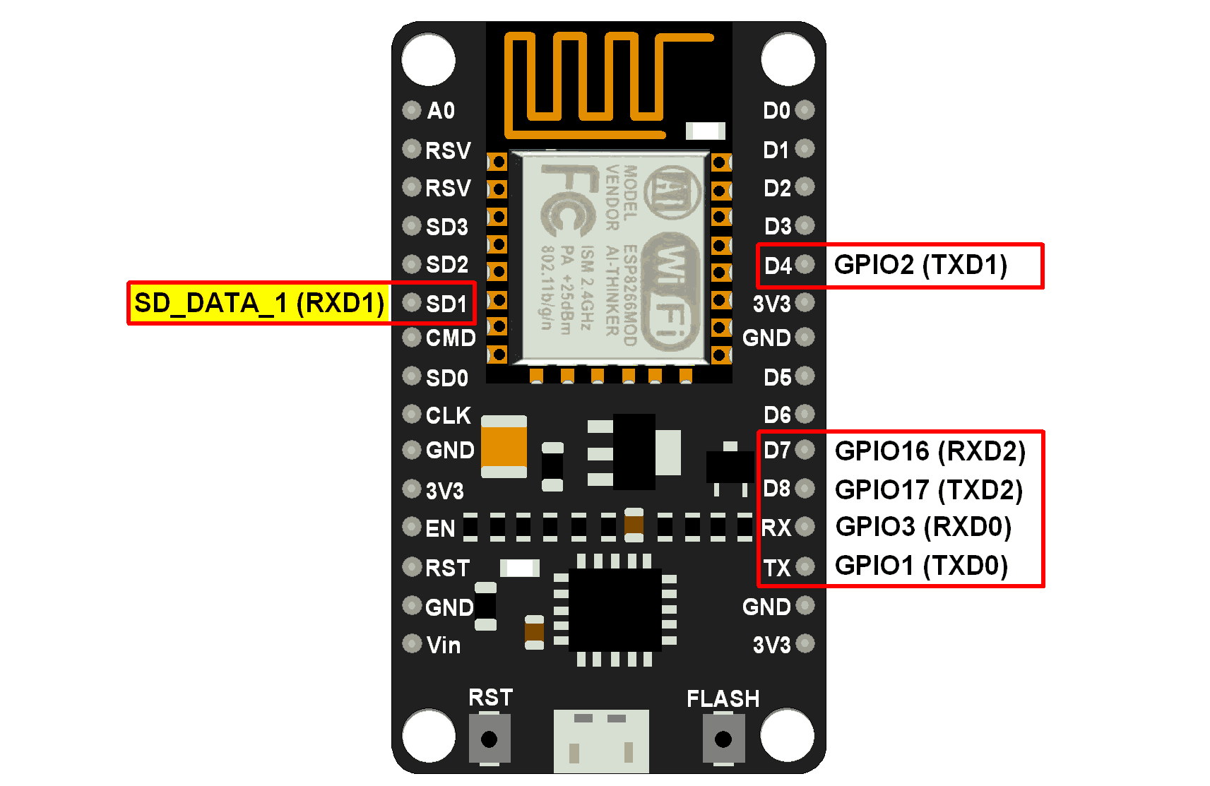
TXD(数据发送引脚)
该引脚用于串行传输数据。
RXD(数据接收引脚)
该引脚用于串行接收数据。
注: SD_DATA_1/RXD1引脚在内部用于 Flash 的 SPI 四路通信。
因此,我们只能使用 UART1 的 TXD1 引脚。
串口使用
日志打印
具体的示例代码如下所示;
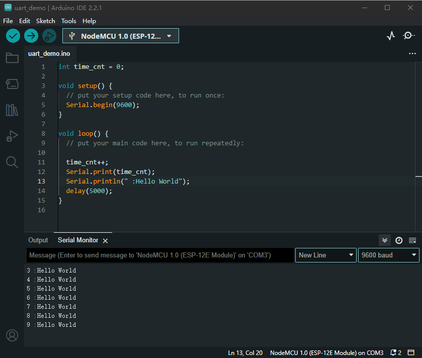
int time_cnt = 0;

void setup() {
  // put your setup code here, to run once:
  Serial.begin(9600);
}

void loop() {
  // put your main code here, to run repeatedly:

  time_cnt++;
  Serial.print(time_cnt);
  Serial.println(" :Hello World");
  delay(5000);
}

- 1
- 2
- 3
- 4
- 5
- 6
- 7
- 8
- 9
- 10
- 11
- 12
- 13
- 14
- 15
- 16
读取数据
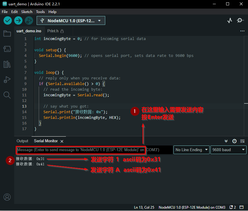
int incomingByte = 0; // for incoming serial data

void setup() {
  Serial.begin(9600); // opens serial port, sets data rate to 9600 bps
}

void loop() {
  // reply only when you receive data:
  if (Serial.available() > 0) {
    // read the incoming byte:
    incomingByte = Serial.read();

    // say what you got:
    Serial.print("接收数据: 0x");
    Serial.println(incomingByte, HEX);
  }
}
- 1
- 2
- 3
- 4
- 5
- 6
- 7
- 8
- 9
- 10
- 11
- 12
- 13
- 14
- 15
- 16
- 17
最终执行结果如下图所示;
常用接口
begin
设置串行数据传输的数据速率(波特率)。
为了与串行监视器通信,请确保使用屏幕右下角菜单中列出的波特率之一。
但是,您可以指定其他速率 - 例如,通过引脚 0 和 1 与需要特定波特率的组件进行通信。
可选的第二个参数配置数据、奇偶校验和停止位。默认为 8 个数据位,无奇偶校验,1 个停止位。
语法
Serial.begin(speed)
Serial.begin(speed, config)
- 1
- 2
示例
void setup() {
    Serial.begin(9600); //设置波特率为9600
}

void loop() {}
- 1
- 2
- 3
- 4
- 5
将数据作为可读性比较好的 ASCII码 文本打印到串口,这个函数打印的效果不带换行。
语法
Serial.print(val)
Serial.print(val, format)
- 1
- 2
- val:需要打印的值
- format:需要打印的数据类型
- DEC:将ASCII打印为十进制数;
- HEX:将ASCII打印为十六进制数;
- OCT:将ASCII打印为八进制数;
- BIN:将ASCII打印为二进制数;
下面详细介绍
示例
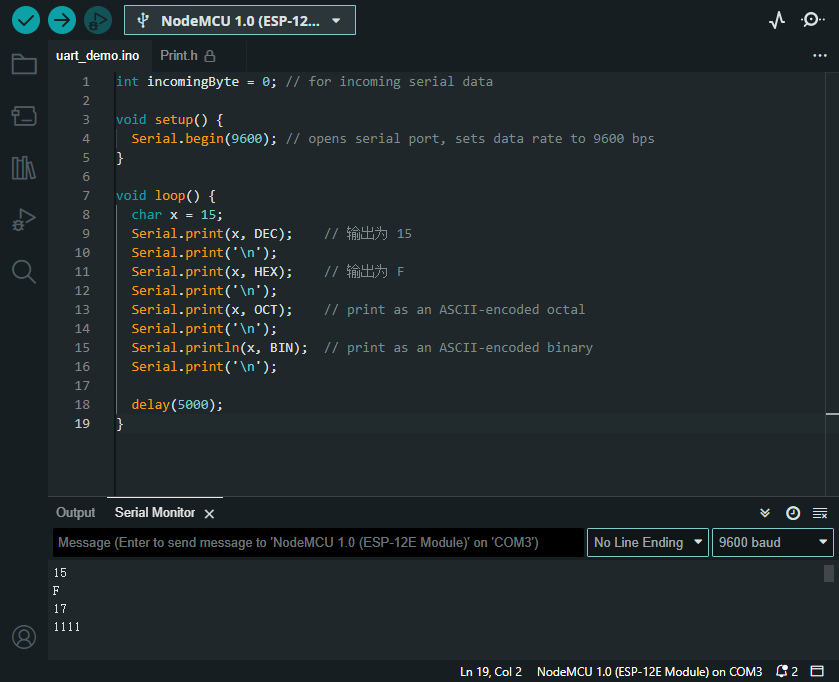
 char x = 15;
 Serial.print(x, DEC);    // 输出为 15
 Serial.print(x, HEX);    // 输出为 F
 Serial.print(x, OCT);    // 输出为 17
 Serial.println(x, BIN);  // 输出为 1111
- 1
- 2
- 3
- 4
- 5
println
将数据作为可读性比较好的 ASCII码 文本打印到串口,在每一行后跟回车符(ASCII码 13 或\r)和换行符(ASCII码 10 或\n”)
在每次打印的内容后面自动追加
\r\n,打印的内容会自动换行。
示例
读取DO端口的模拟值,即ADC数值(将模拟信号转化为数字信号,模数转换器),然后打印到串口,下面是示例代码;
/*
 Analog input reads an analog input on analog in 0, prints the value out.
 created 24 March 2006
 by Tom Igoe
 */

int analogValue = 0;    // variable to hold the analog value

void setup() {
  // open the serial port at 9600 bps:
  Serial.begin(9600);
}

void loop() {
  // read the analog input on pin 0:
  analogValue = analogRead(0);

  // print it out in many formats:
  Serial.println(analogValue);       // print as an ASCII-encoded decimal
  Serial.println(analogValue, DEC);  // print as an ASCII-encoded decimal
  Serial.println(analogValue, HEX);  // print as an ASCII-encoded hexadecimal
  Serial.println(analogValue, OCT);  // print as an ASCII-encoded octal
  Serial.println(analogValue, BIN);  // print as an ASCII-encoded binary

  // delay 10 milliseconds before the next reading:
  delay(10);
}
- 1
- 2
- 3
- 4
- 5
- 6
- 7
- 8
- 9
- 10
- 11
- 12
- 13
- 14
- 15
- 16
- 17
- 18
- 19
- 20
- 21
- 22
- 23
- 24
- 25
- 26
- 27
总结
本文简单介绍了NodeMCU ESP8266 基于Arduino IDE的串口使用详解,以及Serial类的常用接口。
由于作者能力有限,文章中难免存在错误和纰漏,请大胆指正,如果对于文章中存在疑惑或者问题,欢迎在评论区进行留言。
如果文章帮到了你,请帮忙点赞,三连支持
声明:本文内容由网友自发贡献,不代表【wpsshop博客】立场,版权归原作者所有,本站不承担相应法律责任。如您发现有侵权的内容,请联系我们。转载请注明出处:https://www.wpsshop.cn/article/detail/47924

Copyright © 2003-2013 www.wpsshop.cn 版权所有,并保留所有权利。

