- 1python--WebUI自动化_python webui自动化
- 2hive hbase 映射表_presto 查询hive映射hbase
- 3【OpenCV】第十七章: 图像分割与提取_bgdmodel = np.zeros
- 4zoj 3846 GCD Reduce(数论)
- 5计算机网络(全)
- 6python性能分析之log_python複製log和讀取log耗費的電腦資源相同嗎
- 7【Unity】框架设计(三) Odin编辑器窗口扩展,Asset资源的创建和管理(脚本文件创建、预制体、System.IO、AssetDatabase、Selection)_unity odin menueditorwindow
- 8卑微且强大的Gumbel分布
- 9时序预测 | MATLAB实现NARX非线性自回归外生模型房价预测_narx 预测
- 10Windows下深度学习标注工具LabelImg安装和使用指南_win10下安装labelimg
PCIE设备在设备上枚举过程_pcirp
赞
踩
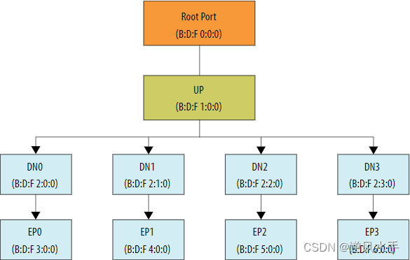
根端口枚举
Root Port (RP)
在枚举过程结束时,Root Port (RP)必须设置以下寄存器:
Primary Bus, Secondary Bus和Subordinate Bus numbers
Memory Base和Limit
IO Base和IO Limit
Max Payload Size
Memory Space Enable bit
Endpoint (EP)
Endpoint (EP)还必须具有由RP设置的以下寄存器:
Master Enable bit
BAR Address
Max Payload Size
Memory Space Enable bit
Severity bit
枚举时候BUS号是深度优先搜索实现

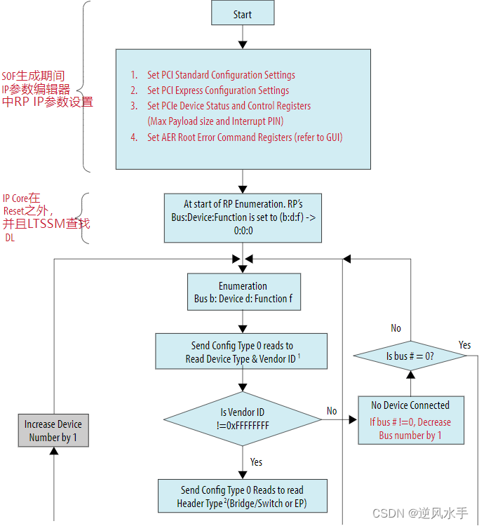
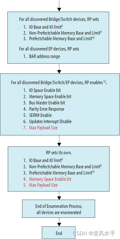
根端口枚举流程图
1.Set PCI Standard Configuration Settings
设置PCI标准配置设置:这指的是设置PCI设备的一些标准配置,例如I/O端口、中断、总线宽度等。这些
配置可以通过PCI配置空间访问,以控制PCI设备的行为。
2.Set PCI Express Configuration Settings
设置PCI Express配置设置:与第一条类似,但是这是针对PCIe设备的配置设置。PCIe是一种高速串行总线技术,用于连接计算机内部的各种设备。
3.Set PCIe Device Status and Control Registers
(Max Payload size and Interrupt PIN)
设置PCIe设备状态和控制寄存器(最大有效荷载大小和中断引脚):这些寄存器用于控制PCIe设备的状态和行为。最大有效荷载大小指的是PCIe设备每次可以发送或接收的数据量的最大值。中断引脚用于指示PCIe设备是否有中断请求。
4.Set AER Root Error Command Registers (refer to GUI)
设置AER(Advanced Error Reporting,高级错误报告)根错误命令寄存器(参考GUI):这些寄存器用于配置AER功能,该功能可以检测和报告PCIe设备的错误情况。GUI(Graphical User Interface,图形用户界面)是一种用户界面,可以帮助用户进行设置和配置。


注释:
对于Header Type 0和Header Type 1,Vendor ID和Device ID位于偏移0x00h。
对于PCIe Gen4,Header Type位于偏移0x0Eh(第二DW)。如果位0设置为1,则表示该器件是一个Bridge(桥接);否则,它是一个EP。如果位7设置为0,表示是一个单一功能器件;否则,它是一个多功能器件。
RP和non-RP器件的capability寄存器清单:
0x34h – Capabilities Pointers。该寄存器用于指向一个由Function实现的capabilities的链接列表:
RP的Capabilities Pointer
Address 40 -标识Power Management Capability ID
Address 50 -标识MSI Capability ID
Address 70 -标识PCI Express Capability结构
non-RP的Capabilities Pointer
Address 40 -标识Power Management Capability ID
Address 48 -标识PCI Express Capability结构
EP没有Primary, Secondary和Subordinate Bus编号相关的寄存器。
Bridge/Switch IO Base和Limit寄存器偏移0x1Ch。这些寄存器是根据PCIe 4.0 Base Specification而设置的。有关更准确的信息和流程,请参阅Base Specification(基本规范)的第7.5.1.3.6章节。
对于EP Type 0头,BAR地址位于以下偏移:
0x10h – Base Address 0
0x14h – Base Address 1
0x18h – Base Address 2
0x1ch – Base Address 3
0x20h – Base Address 4
0x24h – Base Address 5
对于Bridge/Switch Type 1头,BAR地址位于以下偏移:
0x10h – Base Address 0
0x14h – Base Address 1
对于Bridge/Switch Type 1头,IO Base和IO限制寄存器都位于偏移0x1Ch。
对于Bridge/Switch Type 1头,Non-Prefetchable Memory Base和Limit寄存器都位于偏移0x1Ch。
对于Bridge/Switch Type 1头,Prefetchable Memory Base和Limit寄存器都位于偏移0x24h。
对于Bridge/Switch/EP Type 0 & 1头,Bus Master Enable位位于偏移0x04h (Command Register)位2。
对Bridge/Switch/EP Type 0 & 1头,
IO Space Enable位在偏移0x04h (Command Register) 位0。
Memory Space Enable位在偏移0x04h (Command Register)位1。
Bus Master Enable位在偏移0x04h (Command Register)位2。
Parity Error Response位在偏移0x04h (Command Register)位6。
SERR# Enable位在偏移0x04h (Command Register)位8。
Interrupt Disable位在偏移0x04h (Command Register)位10。


