- 1FPGA时钟资源详解(1)——时钟Buffer的选择
- 2鸿蒙原生应用/元服务开发-代理提醒说明(一)
- 3upload-labs通关
- 4Centos7用户管理_在centos7中用户分为哪几种
- 5【机器学习】:脑电数据时域特征提取_mne.io.read_epochs_eeglab
- 6实现字符串的拷贝_实现字符串的拷贝。 void my_strcpy(char * destination,char *
- 7Flutter 数据存储 SharedPreferences_flutter sharedpreferences
- 8鸿蒙HarmonyOS实战-ArkUI组件(Button)_鸿蒙 button
- 9MySQL的zerofill 零填充_mysql中zerofill什么意思
- 10【附源码+论文】基于微信小程序的毕业设计——排课管理系统_网上选排课毕业论文
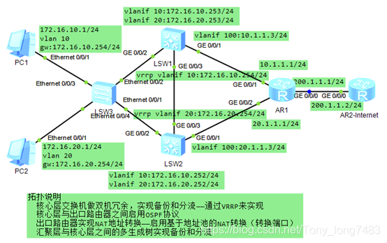
小于1000人且有vlan划分、分层,使用路由协议,生成树和核心交换机都采用冗余和分流的网络设计与配置_1000个监控vlan
赞
踩

1.接入层划分vlan,核心交换机设置vlanif网关
[SW3]vlan batch 10 20
[SW3-Ethernet0/0/3]port link-type access
[SW3-Ethernet0/0/3]port default vlan 10
[SW3-Ethernet0/0/4]port link-type access
[SW3-Ethernet0/0/4]port default vlan 20
[SW3-Ethernet0/0/1]port link-type trunk
[SW3-Ethernet0/0/1]port trunk allow-pass vlan all
[SW3-Ethernet0/0/2]port link-type trunk
[SW3-Ethernet0/0/2]port trunk allow-pass vlan all
[SW1]vlan batch 10 20
[SW1-GigabitEthernet0/0/2]port link-type trunk
[SW1-GigabitEthernet0/0/2]port trunk allow-pass vlan all
[SW1-GigabitEthernet0/0/3]port link-type trunk
[SW1-GigabitEthernet0/0/3]port trunk allow-pass vlan all
[SW1-Vlanif10]ip add 172.16.10.253 24
[SW1-Vlanif10]vrrp vrid 10 virtual-ip 172.16.10.254
[SW1-Vlanif10]vrrp vrid 10 priority 120 //VRRP默认优先级100,越大越优,改为120后,vlan 10优先通过该交换机
[SW1-Vlanif20]ip add 172.16.20.253 24
[SW1-Vlanif20]vrrp vrid 20 virtual-ip 172.16.20.254
[SW2]vlan batch 10 20
[SW2-GigabitEthernet0/0/2]port link-type trunk
[SW2-GigabitEthernet0/0/2]port trunk allow-pass vlan all
[SW2-GigabitEthernet0/0/3]port link-type trunk
[SW2-GigabitEthernet0/0/3]port trunk allow-pass vlan all
[SW2-Vlanif10]ip add 172.16.10.252 24
[SW2-Vlanif10]vrrp vrid 10 virtual-ip 172.16.10.254
[SW2-Vlanif20]ip add 172.16.20.252 24
[SW2-Vlanif20]vrrp vrid 20 virtual-ip 172.16.20.254
[SW2-Vlanif20]vrrp vrid 20 priority 120 // VRRP默认优先级100,越大越优,改为120后,vlan 20优先通过该交换机


2.在接入层和核心层配置MSTP
[SW3]stp mode mstp //华为默认模式
[SW3]stp region-configuration
[SW3-mst-region]region-name net1
[SW3-mst-region]revision-level 1
[SW3-mst-region]instance 1 vlan 10
[SW3-mst-region]instance 2 vlan 20
[SW3-mst-region]active region-configuration
[SW1]stp mode mstp
[SW1]stp region-configuration
[SW1-mst-region]region-name net1
[SW1-mst-region]revision-level 1
[SW1-mst-region]instance 1 vlan 10
[SW1-mst-region]instance 2 vlan 20
[SW1-mst-region]active region-configuration
[SW1]stp instance 1 root primary
[SW1]stp instance 2 root secondary
[SW2]stp mode mstp
[SW2]stp region-configuration
[SW2-mst-region]region-name net1
[SW2-mst-region]revision-level 1
[SW2-mst-region]instance 1 vlan 10
[SW2-mst-region]instance 2 vlan 20
[SW2-mst-region]active region-configuration
[SW2]stp instance 2 root primary
[SW1]stp instance 1 root secondary
[SW2]display stp brief //查看stp
[SW2]display stp
[SW1]display stp instance 1 //查看实例1
3.使用OSPF协议连通核心交换机与出口路由器
[SW1]vlan 100
[SW1-GigabitEthernet0/0/1]port link-type access
[SW1-GigabitEthernet0/0/1]port default vlan 100
[SW1-Vlanif100]ip add 10.1.1.3 24
[SW1-ospf-1-area-0.0.0.0]network 10.1.1.3 0.0.0.255
[SW1-ospf-1-area-0.0.0.0]network 172.6.0.0 0.0.255.255
[SW2]vlan 200
[SW2-GigabitEthernet0/0/1]port link-type access
[SW2-GigabitEthernet0/0/1]port default vlan 200
[SW2-Vlanif200]ip add 20.1.1.3 24
[SW2-ospf-1-area-0.0.0.0]network 20.1.1.3 0.0.0.255
[SW2-ospf-1-area-0.0.0.0]network 172.6.0.0 0.0.255.255
[AR1-ospf-1-area-0.0.0.0]network 10.1.1.1 0.0.0.255
[AR1-ospf-1-area-0.0.0.0]network 20.1.1.1 0.0.0.255
[AR1-ospf-1]default-route-advertise always //下发缺省路由


4.配置出口路由器与外网连通
[AR1-GigabitEthernet0/0/0]ip add 200.1.1.1 24
[AR1]ip route-static 0.0.0.0 0.0.0.0 200.1.1.2
[Internet-GigabitEthernet0/0/0]ip add 200.1.1.2 24
[Internet]ip route-static 172.16.0.0 255.255.0.0 200.1.1.1


5.在AR1上配置基于地址池的NAT转换
[AR1]acl 2000
[AR1-acl-basic-2000]rule permit source 172.16.0.0 0.0.255.255
[AR1]nat address-group 1 200.1.1.10 200.1.1.50
[AR1-GigabitEthernet0/0/0]nat outbound 2000 address-group 1
6.PC可以ping通外网,在AR1的G0/0/0口抓包也看不到内网IP,配置成功


