- 1es--基础--11--es服务API--高亮_es 高亮
- 2用OpenVINO工具包轻松实现PP-OCR实时推理_openvino与paddleoc
- 3C51编程25-应用篇(单片机与电脑端实现wifi通讯)_51单片机wifi模块怎么和上位机连接
- 4微软浏览器Edge打不开怎么办_microsoft edge浏览器打开不了
- 5Android应用开发:移除后置摄像头,仅支持前置摄像头功能_android 代码禁用前置摄像头
- 6Java用JDBC通过远程连接PostgreSQL并实现操作_pgsql server主备 client连接 java
- 7华为机试(JAVA)真题Od【A卷+B卷+C卷+D卷】目录_华为od机试真题
- 8电力系统动态无功优化MATLAB程序基于粒子群算法IEEE33配电网_含分布式电源 无功优化 matlab
- 9戴森
- 10Endnote生成的中英文混排参考文献中“等”与“et al”的处理_国标的参考文献用等还是et al
华为防火墙安全区域及安全策略配置_firewall zone local
赞
踩
- 掌握防火墙安全区域的配置方法
- 掌握安全策略配置方法
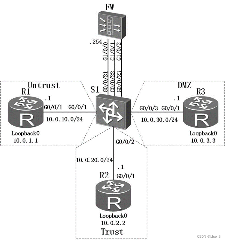
你是你们公司的网络管理员。公司总部的网络分成了三个区域,包括内部区域(Trust)、外部区域(Untrust)和服务器区域(DMZ)。你设计通过防火墙来实现对数据的控制,确保公司内部网络安全,并通过DMZ区域对外网提供服务。
- 登录设备(Console)
1.连接配置口电缆。
a. 关闭FW及配置终端的电源。
b. 通过配置电缆将配置终端的RS-232串口与FW的Console口相连。
c. 经安装检查后上电。
2.超级终端软件的配置(可以从Internet上获取如putty等免费超级终端软件。)。
a. 下载putty软件到本地并双击运行该软件。
b. 选择“Session”,将“Connection type”设置为“Serial”。
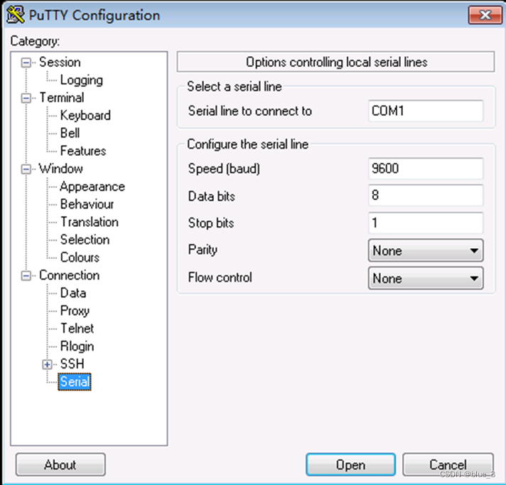
c. 配置通过串口连接设备的参数。具体参数配置如图5所示。
图5 putty软件Serial连接FW参数配置
d. 单击“Open”。
3. 按“Enter”键,按照提示输入缺省管理员账号“admin”和密码“Admin@123”。
4. 修改缺省管理员账号的密码,并进入CLI界面。
说明:为提高安全性,密码必须满足最小复杂度要求,即包含英文大写字母(A~Z)、英文小写字母(a~z)、数字(0~9)、特殊字符(如!、@、#、$、%等)中的三种。
请牢记输入的新密码避免无法登录。
- 基本配置与IP编址
给路由器和防火墙配置地址,并配置静态路由,在交换机上配置VLAN。
<Huawei>system-view
Enter system view, return user view with Ctrl+Z.
[Huawei]sysname R1
[R1]interface GigabitEthernet 0/0/1
[R1-GigabitEthernet0/0/1]ip address 10.0.10.1 24
[R1-GigabitEthernet0/0/1]interface loopback 0
[R1-LoopBack0]ip address 10.0.1.1 24
<Huawei>system-view
Enter system view, return user view with Ctrl+Z.
[Huawei]sysname R2
[R2]interface GigabitEthernet0/0/1
[R2-GigabitEthernet0/0/1]ip address 10.0.20.1 24
[R2-GigabitEthernet0/0/1]interface loopback 0
[R2-LoopBack0]ip address 10.0.2.2 24
<Huawei>system-view
Enter system view, return user view with Ctrl+Z.
[Huawei]sysname R3
[R3]interface GigabitEthernet 0/0/1
[R3-GigabitEthernet0/0/1]ip address 10.0.30.1 24
[R3-GigabitEthernet0/0/1]interface loopback 0
[R3-LoopBack0]ip address 10.0.3.3 24
防火墙默认会启用GigabitEthernet0/0/0接口的ip地址,为避免干扰,可以删除。
<USG6300>system-view
Enter system view, return user view with Ctrl+Z.
[USG6300]sysname FW
[FW]int GigabitEthernet 0/0/0
[FW-GigabitEthernet0/0/0]undo ip address
[FW-GigabitEthernet0/0/0]interface GigabitEthernet 1/0/0
[FW-GigabitEthernet1/0/0]ip address 10.0.10.254 24
[FW-GigabitEthernet1/0/0]interface GigabitEthernet 1/0/1
[FW-GigabitEthernet1/0/1]ip address 10.0.20.254 24
[FW-GigabitEthernet1/0/1]interface GigabitEthernet 1/0/2
[FW-GigabitEthernet1/0/2]ip address 10.0.30.254 24
[FW-GigabitEthernet1/0/2]quit
交换机上需要按照需求定义VLAN。
[Quidway]sysname S1
[S1]vlan batch 11 to 13
[S1]interface GigabitEthernet 0/0/1
[S1-GigabitEthernet0/0/1]port link-type access
[S1-GigabitEthernet0/0/1]port default vlan 11
[S1-GigabitEthernet0/0/1]interface GigabitEthernet 0/0/2
[S1-GigabitEthernet0/0/2]port link-type access
[S1-GigabitEthernet0/0/2]port default vlan 12
[S1-GigabitEthernet0/0/2]interface GigabitEthernet 0/0/3
[S1-GigabitEthernet0/0/3]port link-type access
[S1-GigabitEthernet0/0/3]port default vlan 13
[S1-GigabitEthernet0/0/3]interface GigabitEthernet 0/0/21
[S1-GigabitEthernet0/0/21]port link-type access
[S1-GigabitEthernet0/0/21]port default vlan 11
[S1-GigabitEthernet0/0/21]interface GigabitEthernet 0/0/22
[S1-GigabitEthernet0/0/22]port link-type access
[S1-GigabitEthernet0/0/22]port default vlan 12
[S1-GigabitEthernet0/0/22]interface GigabitEthernet 0/0/23
[S1-GigabitEthernet0/0/23]port link-type access
[S1-GigabitEthernet0/0/23]port default vlan 13
在R1、R2和R3上配置缺省路由,在FW上配置明确的静态路由,实现三个Loopback0接口连接的网段之间路由畅通。
[R1]ip route-static 0.0.0.0 0 10.0.10.254
[R2]ip route-static 0.0.0.0 0 10.0.20.254
[R3]ip route-static 0.0.0.0 0 10.0.30.254
[FW]ip route-static 10.0.1.0 24 10.0.10.1
[FW]ip route-static 10.0.2.0 24 10.0.20.1
[FW]ip route-static 10.0.3.0 24 10.0.30.1
配置完成后检查防火墙路由信息。
[FW]display ip routing-table
Route Flags: R - relay, D - download to fib
------------------------------------------------------------------------------
Routing Tables: Public
Destinations : 11 Routes : 11
Destination/Mask Proto Pre Cost Flags NextHop Interface
10.0.1.0/24 Static 60 0 RD 10.0.10.1 GigabitEthernet1/0/0
10.0.2.0/24 Static 60 0 RD 10.0.20.1 GigabitEthernet1/0/1
10.0.3.0/24 Static 60 0 RD 10.0.30.1 GigabitEthernet1/0/2
10.0.10.0/24 Direct 0 0 D 10.0.10.254 GigabitEthernet1/0/0
10.0.10.254/32 Direct 0 0 D 127.0.0.1 InLoopBack0
10.0.20.0/24 Direct 0 0 D 10.0.20.254 GigabitEthernet1/0/1
10.0.20.254/32 Direct 0 0 D 127.0.0.1 InLoopBack0
10.0.30.0/24 Direct 0 0 D 10.0.30.254 GigabitEthernet1/0/2
10.0.30.254/32 Direct 0 0 D 127.0.0.1 InLoopBack0
127.0.0.0/8 Direct 0 0 D 127.0.0.1 InLoopBack0
127.0.0.1/32 Direct 0 0 D 127.0.0.1 InLoopBack0
- 配置防火墙区域
防火墙上默认有四个区域,分别是“local“、”trust“、”untrust“、”dmz“。实验中我们使用到“trust“、”untrust“和”dmz“三个区域,分别将对应接口加入各安全区域,由于默认配置将GE0/0/0加入了“trust”区域,为避免干扰,将其删除。
[FW]firewall zone dmz
[FW-zone-dmz]add interface GigabitEthernet 1/0/2
[FW-zone-dmz]firewall zone trust
[FW-zone-trust]add interface GigabitEthernet 1/0/1
[FW-zone-trust]undo add interface GigabitEthernet 0/0/0
[FW-zone-trust]fire zone untrust
[FW-zone-untrust]add interface GigabitEthernet 1/0/0
[FW-zone-untrust]quit
检查各接口的区域:
[FW]display zone interface
local
#
trust
interface of the zone is (1):
GigabitEthernet1/0/1
#
untrust
interface of the zone is (1):
GigabitEthernet1/0/0
#
dmz
interface of the zone is (1):
GigabitEthernet1/0/2
#
检查各区域的优先级:
[FW]display zone
local
priority is 100
#
trust
priority is 85
interface of the zone is (1):
GigabitEthernet1/0/1
#
untrust
priority is 5
interface of the zone is (1):
GigabitEthernet1/0/0
#
dmz
priority is 50
interface of the zone is (1):
GigabitEthernet1/0/2
#
可以看到三个接口已经被划分到相应的区域内,默认情况下不同区域间是不可互通的,因此此时路由器之间流量无法通过。
- 配置安全策略
如果防火墙域间没有配置安全策略,或查找安全策略时,所有的安全策略都没有命中,则默认执行域间的缺省包过滤动作(拒绝通过)。
配置安全策略,仅允许Trust区域访问其他区域,不允许其他区域之间的访问。
[FW]security-policy
[FW-policy-security]rule name policy_sec_1
[FW-policy-security-rule-policy_sec_1]source-zone trust
[FW-policy-security-rule-policy_sec_1]destination-zone untrust
[FW-policy-security-rule-policy_sec_1]action permit
[FW-policy-security-rule-policy_sec_1]rule name policy_sec_2
[FW-policy-security-rule-policy_sec_2]source-zone trust
[FW-policy-security-rule-policy_sec_2]destination-zone dmz
[FW-policy-security-rule-policy_sec_2]action permit
[FW-policy-security-rule-policy_sec_2]quit
[FW-policy-security]quit
检查配置结果:
[FW]display security-policy all
Total:3
RULE ID RULE NAME STATE ACTION HITTED
-------------------------------------------------------------------------------
0 default enable deny 0
1 policy_sec_1 enable permit 0
2 policy_sec_2 enable permit 0
-------------------------------------------------------------------------------
[FW]display security-policy rule policy_sec_1
(0 times matched)
rule name policy_sec_1
source-zone trust
destination-zone untrust
action permit
[FW]display security-policy rule policy_sec_2
(0 times matched)
rule name policy_sec_2
source-zone trust
destination-zone dmz
action permit
检查从trust到untrust和dmz的连通性:
[R2]ping -a 10.0.2.2 10.0.1.1
PING 10.0.1.1: 56 data bytes, press CTRL_C to break
Reply from 10.0.1.1: bytes=56 Sequence=1 ttl=254 time=1 ms
Reply from 10.0.1.1: bytes=56 Sequence=2 ttl=254 time=1 ms
Reply from 10.0.1.1: bytes=56 Sequence=3 ttl=254 time=1 ms
Reply from 10.0.1.1: bytes=56 Sequence=4 ttl=254 time=1 ms
Reply from 10.0.1.1: bytes=56 Sequence=5 ttl=254 time=1 ms
--- 10.0.1.1 ping statistics ---
5 packet(s) transmitted
5 packet(s) received
0.00% packet loss
round-trip min/avg/max = 1/1/1 ms
[R2]ping -a 10.0.2.2 10.0.3.3
PING 10.0.3.3: 56 data bytes, press CTRL_C to break
Reply from 10.0.3.3: bytes=56 Sequence=1 ttl=254 time=1 ms
Reply from 10.0.3.3: bytes=56 Sequence=2 ttl=254 time=1 ms
Reply from 10.0.3.3: bytes=56 Sequence=3 ttl=254 time=1 ms
Reply from 10.0.3.3: bytes=56 Sequence=4 ttl=254 time=1 ms
Reply from 10.0.3.3: bytes=56 Sequence=5 ttl=254 time=1 ms
--- 10.0.3.3 ping statistics ---
5 packet(s) transmitted
5 packet(s) received
0.00% packet loss
round-trip min/avg/max = 1/1/1 ms
检查从untrust到trust和dmz的连通性:
[R1]ping -a 10.0.1.1 10.0.2.2
PING 10.0.2.2: 56 data bytes, press CTRL_C to break
Request time out
Request time out
Request time out
Request time out
Request time out
--- 10.0.2.2 ping statistics ---
5 packet(s) transmitted
0 packet(s) received
100.00% packet loss
[R1]ping -a 10.0.1.1 10.0.3.3
PING 10.0.3.3: 56 data bytes, press CTRL_C to break
Request time out
Request time out
Request time out
Request time out
Request time out
--- 10.0.3.3 ping statistics ---
5 packet(s) transmitted
0 packet(s) received
100.00% packet loss
检查从dmz到untrust和trust的连通性:
[R3]ping -a 10.0.3.3 10.0.1.1
PING 10.0.1.1: 56 data bytes, press CTRL_C to break
Request time out
Request time out
Request time out
Request time out
Request time out
--- 10.0.1.1 ping statistics ---
5 packet(s) transmitted
0 packet(s) received
100.00% packet loss
[R3]ping -a 10.0.3.3 10.0.2.2
PING 10.0.2.2: 56 data bytes, press CTRL_C to break
Request time out
Request time out
Request time out
Request time out
Request time out
--- 10.0.2.2 ping statistics ---
5 packet(s) transmitted
0 packet(s) received
100.00% packet loss
经过验证,以trust区域为源的数据可以访问untrust和dmz,但以其他区域为源的数据不能互访。
配置域间包过滤策略,允许Untrust区域访问DMZ区域的特定服务器。
DMZ区域有一个服务器,IP地址为10.0.3.3,需要对Untrust区域开放Telnet服务。同时为了测试网络,需要开放ICMP Ping测试功能。
[FW-policy-security-rule-policy_sec_3]source-zone untrust
[FW-policy-security-rule-policy_sec_3]destination-zone dmz
[FW-policy-security-rule-policy_sec_3]destination-address 10.0.3.3 mask 255.255.255.255
[FW-policy-security-rule-policy_sec_3]service icmp
[FW-policy-security-rule-policy_sec_3]service telnet
[FW-policy-security-rule-policy_sec_3]action permit
为了能在进行Telnet测试,在R3上开启Telnet功能。
[R3]telnet server enable
[R3]aaa
[R3-aaa]local-user test password irreversible-cipher Admin@123 Admin@123
[R3-aaa]local-user test service-type telnet
[R3-aaa]quit
[R3]user-interface vty 0 4
[R3-ui-vty0-4]authentication-mode aaa
[R3-ui-vty0-4]protocol inbound telnet
测试从R1(untrust)到R3(dmz)的ping和telnet:
<R1>ping 10.0.3.3
PING 10.0.3.3: 56 data bytes, press CTRL_C to break
Reply from 10.0.3.3: bytes=56 Sequence=1 ttl=254 time=1 ms
Reply from 10.0.3.3: bytes=56 Sequence=2 ttl=254 time=1 ms
Reply from 10.0.3.3: bytes=56 Sequence=3 ttl=254 time=1 ms
Reply from 10.0.3.3: bytes=56 Sequence=4 ttl=254 time=1 ms
Reply from 10.0.3.3: bytes=56 Sequence=5 ttl=254 time=1 ms
--- 10.0.3.3 ping statistics ---
5 packet(s) transmitted
5 packet(s) received
0.00% packet loss
round-trip min/avg/max = 1/1/1 ms
<R1>ping 10.0.30.1
PING 10.0.30.1: 56 data bytes, press CTRL_C to break
Request time out
Request time out
Request time out
Request time out
Request time out
--- 10.0.30.1 ping statistics ---
5 packet(s) transmitted
0 packet(s) received
100.00% packet loss
<R1>telnet 10.0.3.3
Press CTRL_] to quit telnet mode
Trying 10.0.3.3 ...
Connected to 10.0.3.3 ...
Login authentication
Username:test
Password:
-----------------------------------------------------------------------------
User last login information:
-----------------------------------------------------------------------------
Access Type: Telnet
IP-Address : 10.0.10.1
Time : 2016-09-25 03:29:23+00:00
-----------------------------------------------------------------------------
<R3>quit
Info:Configuration console exit, please retry to log on
The connection was closed by the remote host
<R1>telnet 10.0.30.1
Press CTRL_] to quit telnet mode
Trying 10.0.30.1 ...
Error: Can't connect to the remote host
<R1>
根据验证可知,只有访问指定地址的icmp和telnet可以通过,其他流量全部禁止。
<S1>display current-configuration
!Software Version V200R008C00SPC500
#
sysname S1
#
vlan batch 11 to 13
#
interface GigabitEthernet0/0/1
port link-type access
port default vlan 11
#
interface GigabitEthernet0/0/2
port link-type access
port default vlan 12
#
interface GigabitEthernet0/0/3
port link-type access
port default vlan 13
#
interface GigabitEthernet0/0/21
port link-type access
port default vlan 11
#
interface GigabitEthernet0/0/22
port link-type access
port default vlan 12
#
interface GigabitEthernet0/0/23
port link-type access
port default vlan 13
#
return
<R1>display current-configuration
[V200R007C00SPC600]
#
sysname R1
#
interface GigabitEthernet0/0/1
ip address 10.0.10.1 255.255.255.0
#
interface LoopBack0
ip address 10.0.1.1 255.255.255.0
#
ip route-static 0.0.0.0 0.0.0.0 10.0.10.254
#
return
<R2>display current-configuration
[V200R007C00SPC600]
#
sysname R2
#
interface GigabitEthernet0/0/1
ip address 10.0.20.1 255.255.255.0
#
interface LoopBack0
ip address 10.0.2.2 255.255.255.0
#
ip route-static 0.0.0.0 0.0.0.0 10.0.20.254
#
return
<R3>display current-configuration
[V200R007C00SPC600]
#
sysname R3
#
aaa
local-user test password irreversible-cipher Admin@123
local-user test privilege level 0
local-user test service-type telnet
#
interface GigabitEthernet0/0/1
ip address 10.0.30.1 255.255.255.0
#
interface LoopBack0
ip address 10.0.3.3 255.255.255.0
#
telnet server enable
#
ip route-static 0.0.0.0 0.0.0.0 10.0.30.254
#
user-interface vty 0 4
authentication-mode aaa
protocol inbound telnet
#
return
<FW>display current-configuration
#
sysname FW
#
interface GigabitEthernet1/0/0
ip address 10.0.10.254 255.255.255.0
#
interface GigabitEthernet1/0/1
ip address 10.0.20.254 255.255.255.0
#
interface GigabitEthernet1/0/2
ip address 10.0.30.254 255.255.255.0
#
firewall zone local
set priority 100
#
firewall zone trust
set priority 85
add interface GigabitEthernet1/0/1
#
firewall zone untrust
set priority 5
add interface GigabitEthernet1/0/0
#
firewall zone dmz
set priority 50
add interface GigabitEthernet1/0/2
#
ip route-static 10.0.1.0 255.255.255.0 10.0.10.1
ip route-static 10.0.2.0 255.255.255.0 10.0.20.1
ip route-static 10.0.3.0 255.255.255.0 10.0.30.1
#
security-policy
rule name policy_sec_1
source-zone trust
destination-zone untrust
action permit
rule name policy_sec_2
source-zone trust
destination-zone dmz
action permit
rule name policy_sec_3
source-zone untrust
destination-zone dmz
destination-address 10.0.3.3 mask 255.255.255.255
service icmp
service telnet
action permit
#
return


