- 1撞库攻击是什么,如何进行有效的防护阻止
- 2嵌入式人工智能应用-第三章 opencv操作1
- 3netbeans中add server instance界面为什么让创建一个user
- 4docker搭建hbase环境_docker 安装hbase
- 5【华为 ICT & HCIA & eNSP 习题汇总】——题目集20
- 6开源聊天软件和 php版本的开源聊天软件的介绍
- 7Python如何读取Excel表内容_python读取excel数据
- 8GitBook+Markdown制作精美电子书_gitbook将markdown文件以文档网页的形式
- 9Python爬取B站排行榜前100视频信息,超详细
- 10Visual Studio 2017安装和项目配置_vs2017
使用eNSP配置MGRE实验
赞
踩
一、实验拓扑
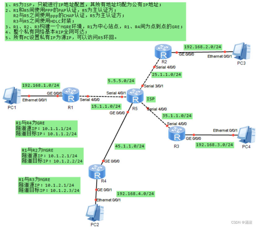
二、实验要求
1、R5为ISP,只能进行IP地址配置,其所有地址均配为公有IP地址;
2、R1和R5间使用PPP的PAP认证,R5为主认证方;R2与R5之间使用ppp的CHAP认证,R5为主认证方;
R3与R5之间使用HDLC封装;
3、R1、R2、R3构建一个MGRE环境,R1为中心站点,R1、R4间为点到点的GRE;4、整个私有网络基本RIP全网可达;
5、所有pc设置私有IP为源IP,可以访问R5环回。
三、实验划分
划分IP
R1:
R2:
R3:
R4:
ISP:
四、实验配置
1)、使全网通畅
1、配置IP
R1:
- [R1]int g 0/0/0
- [R1-GigabitEthernet0/0/0]ip ad 192.168.1.1 24
- [R1-GigabitEthernet0/0/0]int s 4/0/0
- [R1-Serial4/0/0]ip ad 15.1.1.1 24
R2:
- [R2]int g 0/0/0
- [R2-GigabitEthernet0/0/0]ip ad 192.168.2.1 24
- [R2-GigabitEthernet0/0/0]int s 4/0/0
- [R2-Serial4/0/0]ip ad 25.1.1.1 24
R3:
- [R3]int g 0/0/0
- [R3-GigabitEthernet0/0/0]ip ad 192.168.3.1 24
- [R3-GigabitEthernet0/0/0]int s 4/0/0
- [R3-Serial4/0/0]ip ad 35.1.1.1 24
R4:
- [R4]int g 0/0/0
- [R4-GigabitEthernet0/0/0]ip ad 45.1.1.1 24
- [R4-GigabitEthernet0/0/0]int g0/0/1
- [R4-GigabitEthernet0/0/1]ip ad 192.168.4.1 24
ISP:
- [ISP]int s4/0/1
- [ISP-Serial4/0/1]ip ad 15.1.1.2 24
- [ISP-Serial4/0/1]int s3/0/1
- [ISP-Serial3/0/1]ip ad 25.1.1.2 24
- [ISP-Serial3/0/1]int s4/0/0
- [ISP-Serial4/0/0]ip ad 35.1.1.2 24
- [ISP-Serial4/0/0]int g 0/0/0
- [ISP-GigabitEthernet0/0/0]ip ad 45.1.1.1 24
- [ISP-GigabitEthernet0/0/0]int l0
- [ISP-LoopBack0]ip ad 5.5.5.5 24
2、配置缺省路由
R1:
[R1]ip route-static 0.0.0.0 0 15.1.1.2R2:
[R2]ip route-static 0.0.0.0 0 25.1.1.2R3:
[R3]ip route-static 0.0.0.0 0 35.1.1.2R4:
[R4]ip route-static 0.0.0.0 0 45.1.1.23、测试是否全网通

2)、R1和R5间使用PPP的PAP认证,R5为主认证方
1、认证方ISP:
在aaa中申请用户名和密码
- [ISP]aaa
- [ISP-aaa]local-user dumj password cipher 123456
设置服务类型为ppp
[ISP-aaa]local-user dumj service-type ppp在接口做pap认证
[ISP-Serial4/0/1]ppp authentication-mode pap2、被认证方:
[R1-Serial4/0/0]ppp pap local-user dumj password cipher 1234563、验证
重启接口
- [R1-Serial4/0/0]shutdown
- [R1-Serial4/0/0]undo shutdown
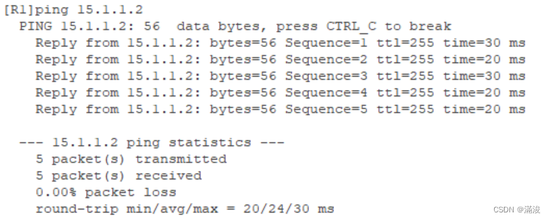
ping测试
3)、R2与R5之间使用ppp的CHAP认证,R5为主认证方
1、认证方R5在接口做CHAP认证
- [ISP]int s3/0/1
- [ISP-Serial3/0/1]ppp authentication-mode chap
2、被验证方R2
- [R2]int s4/0/0
- [R2-Serial4/0/0]ppp chap user dumj
- [R2-Serial4/0/0]ppp chap password cipher 123456
3、验证
重启接口
- [R2-Serial4/0/0]shutdown
- [R2-Serial4/0/0]undo shutdown
ping测试
4)、R3/R5之间使用HDLC封装
更改R3/R5接口的协议类型为HDLC即可
- [R3-Serial4/0/0]link-protocol hdlc
- [ISP-Serial4/0/0]link-protocol hdlc
五、以R1为中心,建立R1/R2/R3的MGRE环境
令隧道接口的虚拟网段为 192.168.5.0/24
1. 中心R1:
创建隧道接口并配置IP为192.168.5.1/24
- [R1]interface Tunnel 0/0/0
- [R1-Tunnel0/0/0]ip address 192.168.5.1 24
定义封装方式
[R1-Tunnel0/0/0]tunnel-protocol gre p2mp定义封装的源IP
[R1-Tunnel0/0/0]source 15.0.0.1创建NHRP域
[R1-Tunnel0/0/0]nhrp network-id 1002.分支R2:
创建隧道接口并配置IP为192.168.5.2/24
- [R2]interface Tunnel 0/0/0
- [R2-Tunnel0/0/0]ip address 192.168.5.2 24
定义封装方式
[R2-Tunnel0/0/0]tunnel-protocol gre p2mp定义封装的源接口
[R2-Tunnel0/0/0]source Serial 4/0/0创建NHRP域
[R2-Tunnel0/0/0]nhrp network-id 100找中心上报映射信息
[R2-Tunnel0/0/0]nhrp entry 192.168.5.1 15.0.0.1 register 3.R2同理R3配置
六、建立R1/R4的GRE环境
令隧道接口的虚拟网段为 192.168.6.0/24
1. 在R1上:
1)创建隧道接口并配置IP为192.168.6.1/24
- [R1]interface Tunnel 0/0/1
- [R1-Tunnel0/0/1]ip address 192.168.6.1 24
2)定义封装方式
[R1-Tunnel0/0/1]tunnel-protocol gre
3)定义封装内容
- [R1-Tunnel0/0/1]source 15.0.0.1
- [R1-Tunnel0/0/1]destination 45.0.0.1
2. 在R4上:
1)创建隧道接口并配置IP为192.168.6.2/24
- [R4]interface Tunnel 0/0/0
- [R4-Tunnel0/0/0]ip address 192.168.6.2 24
2)定义封装方式
[R4-Tunnel0/0/0]tunnel-protocol gre
3)定义封装内容
- [R4-Tunnel0/0/0]source 45.0.0.1
- [R4-Tunnel0/0/0]destination 15.0.0.1
七、整个私网配置RIP全网可达
1. R1配置:
1)开启R1伪广播
[R1-Tunnel0/0/0]nhrp entry multicast dynamic
2)关闭RIP的水平分割
[R1-Tunnel0/0/0]undo rip split-horizon
3)进入RIP进程,选择版本
- [R1]rip
- [R1-rip-1]version 2
4)宣告
- [R1-rip-1]network 192.168.1.0
- [R1-rip-1]network 192.168.5.0
- [R1-rip-1]network 192.168.6.0
2. R2/R3/R4配置:
- [R2]rip
- [R2-rip-1]version 2
- [R2-rip-1]network 192.168.2.0
- [R2-rip-1]network 192.168.5.0
- [R3]rip
- [R3-rip-1]version 2
- [R3-rip-1]network 192.168.3.0
- [R3-rip-1]network 192.168.5.0
- [R4]rip
- [R4-rip-1]version 2
- [R4-rip-1]network 192.168.4.0
- [R4-rip-1]network 192.168.6.0
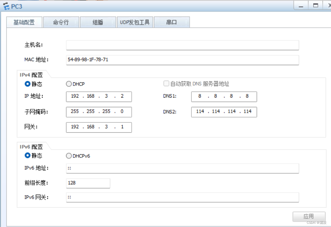
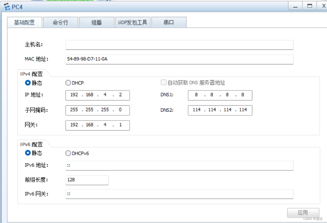
八、为所有PC配置私有IP,均可访问R5的环回
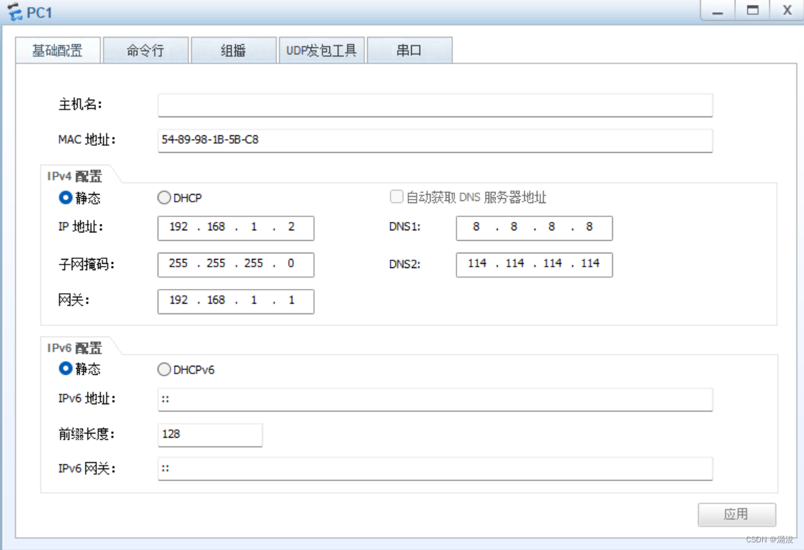
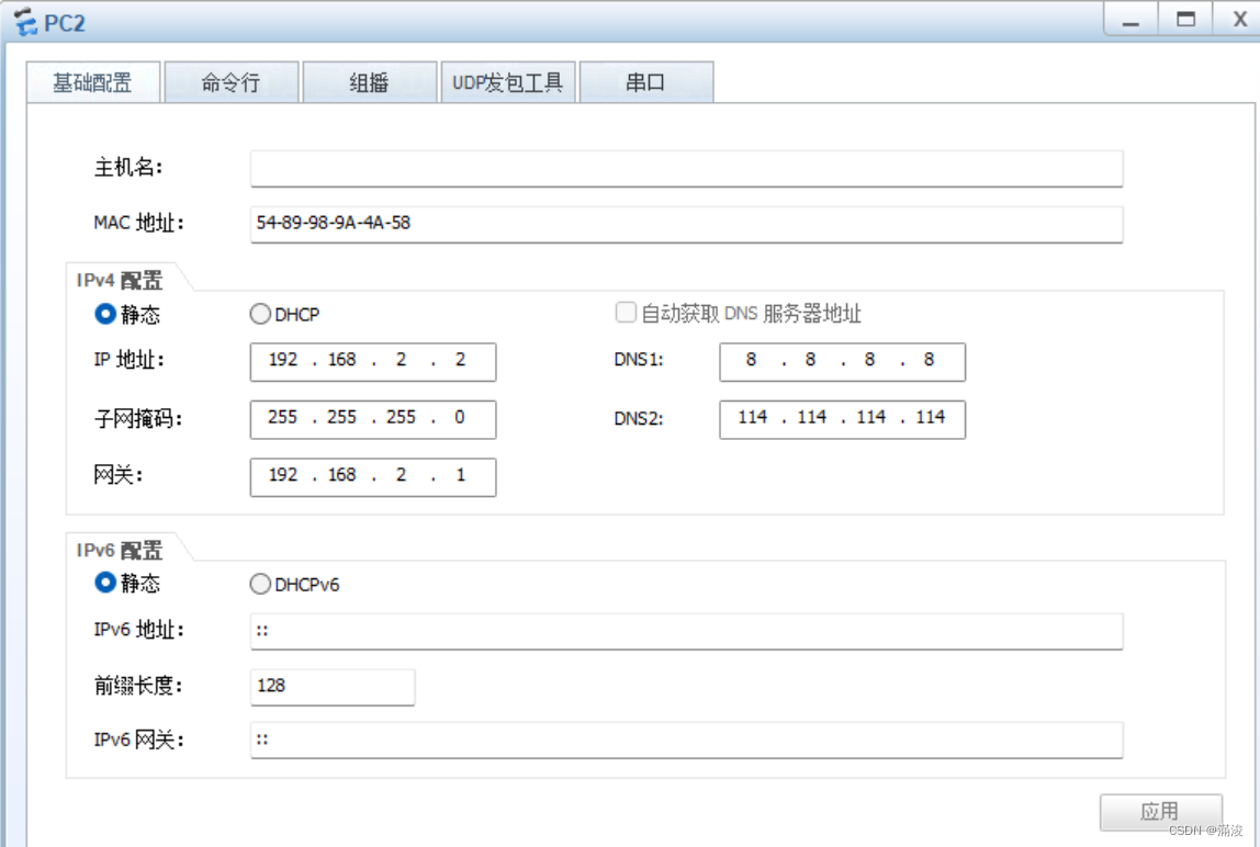
1. 为PC配置IP
2. 配置NAT easyIP
- [R1]acl 2000
- [R1-acl-basic-2000]rule 10 permit source 192.168.1.0 0.0.0.255
- [R1-acl-basic-2000]q
- [R1]interface Serial 4/0/0
- [R1-Serial4/0/0]nat outbound 2000
- [R2]acl 2000
- [R2-acl-basic-2000]rule 10 permit source 192.168.2.0 0.0.0.255
- [R2-acl-basic-2000]q
- [R2]interface Serial 4/0/0
- [R2-Serial4/0/0]nat outbound 2000
- [R3]acl 2000
- [R3-acl-basic-2000]rule 10 permit source 192.168.3.0 0.0.0.255
- [R3-acl-basic-2000]q
- [R3]interface Serial 4/0/0
- [R3-Serial4/0/0]nat outbound 2000
- [R4]acl 2000
- [R4-acl-basic-2000]rule 10 permit source 192.168.4.0 0.0.0.255
- [R4-acl-basic-2000]q
- [R4]interface GigabitEthernet 0/0/0
- [R4-GigabitEthernet0/0/0]nat outbound 2000


