
- 1Vue动态路由的后端实现(基于AOP的思路)_vue让两个方法 一个路由 后端如何指向
- 2easyexcel 导入_easyexcel导入
- 3Jetson nano之ROS入门- -ROS集成开发搭建与ROS通信学习笔记_jetson ros
- 4Spring-AOP
- 5jdk8的十大新特性_jdk8 watchservice
- 6当CMOS遇上TTL_ttl和cmos扇出数
- 72.4.4 代理一个TCP客户端(示例补充)
- 8Vue与React区别与优缺点_vue和react区别
- 9虚拟机内使用 archinstall 安装 arch linux 2024.01.01
- 10aardio - API调用分析_aardio 可以做数据分析吗
stm32f407探索者开发板(十七)——串口寄存器库函数配置方法_stm32串口5 sr dr 寄存器
赞
踩
一、STM32串口常用寄存器和库函数
1.1 常用的串口寄存器
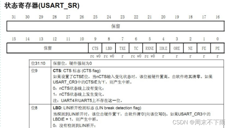
USART_ SR状态寄存器
USART_ DR数据寄存器
USART_BRR波特率寄存器
1.2 串口相关的库函数
void USART_ Init();           //串口初始化:波特率,数据字长,奇偶校验,硬件流控以及收发使能
void USART Cmd();             //使能串口
void USART ITConfig0;         //使能相关中断

void USART SendData();        //发送数据到串口,DR
uint16 t USART ReceiveData(); //接受数据,从DR读取接受到的数据

FlagStatus USART GetFlagStatus(); //获取状态标志位
void USART ClearFlag();           //清除状态标志位
ITStatus USART GetlTStatus);      //获取中断状态标志位
void USART_ ClearlTPendingBit);   //清除中断状态标志位
- 1
- 2
- 3
- 4
- 5
- 6
- 7
- 8
- 9
- 10
- 11
- 12
1.3 状态寄存器(USART_ SR)
所用函数
FlagStatus USART_GetFlagStatus(USART TypeDef USARTx; uint16 t USART_FLAG);
FlagStatus USART_GetFlagStatus(USART_TypeDef* USARTx, uint16_t USART_FLAG)
{
  FlagStatus bitstatus = RESET;
  /* Check the parameters */
  assert_param(IS_USART_ALL_PERIPH(USARTx));
  assert_param(IS_USART_FLAG(USART_FLAG));

  /* The CTS flag is not available for UART4 and UART5 */
  if (USART_FLAG == USART_FLAG_CTS)
  {
    assert_param(IS_USART_1236_PERIPH(USARTx));
  }

  if ((USARTx->SR & USART_FLAG) != (uint16_t)RESET)
  {
    bitstatus = SET;
  }
  else
  {
    bitstatus = RESET;
  }
  return bitstatus;
}

- 1
- 2
- 3
- 4
- 5
- 6
- 7
- 8
- 9
- 10
- 11
- 12
- 13
- 14
- 15
- 16
- 17
- 18
- 19
- 20
- 21
- 22
- 23
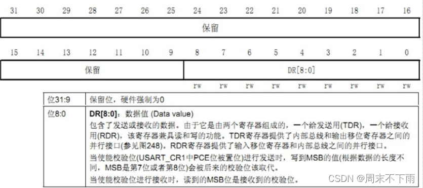
1.4 数据寄存器(USART_ DR)
相关函数
void USART SendData(USART TypeDef* USARTx, uint16 t Data);
uint16_t USART_ ReceiveData(USARTTypeDef* USARTx)
void USART_SendData(USART_TypeDef* USARTx, uint16_t Data)
{
  /* Check the parameters */
  assert_param(IS_USART_ALL_PERIPH(USARTx));
  assert_param(IS_USART_DATA(Data));

  /* Transmit Data */
  USARTx->DR = (Data & (uint16_t)0x01FF);
}
- 1
- 2
- 3
- 4
- 5
- 6
- 7
- 8
- 9
- 10
uint16_t USART_ReceiveData(USART_TypeDef* USARTx)
{
  /* Check the parameters */
  assert_param(IS_USART_ALL_PERIPH(USARTx));

  /* Receive Data */
  return (uint16_t)(USARTx->DR & (uint16_t)0x01FF);
}
- 1
- 2
- 3
- 4
- 5
- 6
- 7
- 8
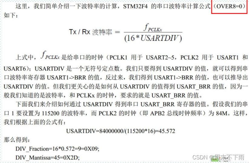
1.5 波特率寄存器(USART_BRR)
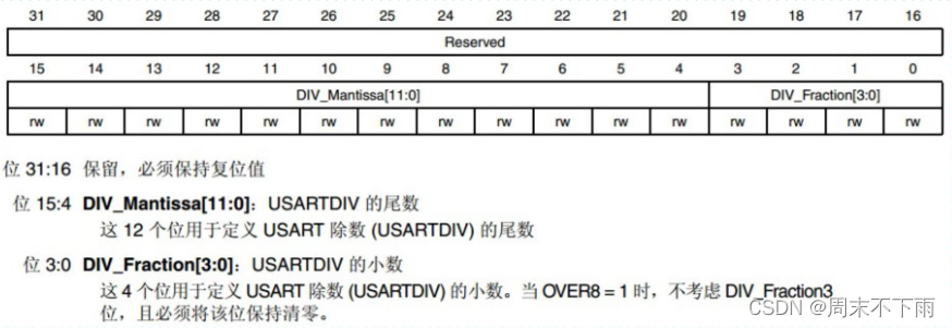
关于波特率的计算
小数部分需要乘上16
void USART Init(USART TypeDef* USARTx; USART_ InitTypeDef* USART: InitStruct)
第一个入口参数是用来确实是哪个串口
#define IS_USART_ALL_PERIPH(PERIPH) (((PERIPH) == USART1) || \
                                     ((PERIPH) == USART2) || \
                                     ((PERIPH) == USART3) || \
                                     ((PERIPH) == UART4)  || \
                                     ((PERIPH) == UART5)  || \
                                     ((PERIPH) == USART6) || \
                                     ((PERIPH) == UART7)  || \
                                     ((PERIPH) == UART8)) 1-8个
- 1
- 2
- 3
- 4
- 5
- 6
- 7
- 8
第二个入口参数结构体,就是设置串口的一些变量
typedef struct
{
  uint32_t USART_BaudRate;            //设置波特率
  uint16_t USART_WordLength;          //设置字长,8/9
  uint16_t USART_StopBits;            //停止位
  uint16_t USART_Parity;              //奇偶校验
  uint16_t USART_Mode;                //使能发送/控制
  uint16_t USART_HardwareFlowControl; //硬件控制(本次不用)
} USART_InitTypeDef;
- 1
- 2
- 3
- 4
- 5
- 6
- 7
- 8
- 9
二、串口配置一般步骤
①串口时钟使能: RCC_APBxPeriphClockCmd);
GPIO时钟使能: RCC_ AHB1PeriphClockCmd();
②引脚复用映射:GPIO_PinAFConfig();
③GPIO端口模式设置:GPIO _Init(); 模式设置为GPIO_Mode_ AF
④串口参数初始化: USART_ Init();
⑤开启中断并且初始化NVIC ( 如果需要开启中断才需要这个步骤)
NVIC_ Init();
USART_ITConfig();
⑥使能串口:USART_Cmd();
⑦编写中断处理函数: USARTX_ IRQHandler();
⑧串口数据收发:
void USART_SendData();//发送数据到串口,DR
uint16_ t USART_ReceiveData();//接受数据,从DR读取接受到的数据
⑨串口传输状态获取:
FlagStatus USART_GetFlagStatus();
void USART_ClearlTPendingBit();
- stm32串口连接esp8266WiFi模块,通过AT指令控制模块进行数据收发,和服务器进行通讯。可以用于单片机直接的通信,手机和单片机通讯等。_基于stm32、esp8266及ov7670的无线图传下位机源码基于stm32、esp8266... [详细]
赞
踩
 使用STM32作为控制器,ULN2003作为驱动模块驱动28BYJ-48步进电机,可实现通过按键控制电机以不同速度转过不同角度……_步进电机uln2003步进电机uln2003本篇文章包含的内容一、步进电机的结构和工作原理1.1步进控制系统... [详细]
赞
踩
 欢迎来到我的博客。今天我想向大家介绍一下STM32软件I2C功能。首先,让我们来了解一下I2C(Inter-IntegratedCircuit)总线。I2C是一种串行通信总线,最初由Philips公司开发。它允许多个设备使用同一条总线进行通... [详细]
赞
踩
- 本篇文章介绍了在STM32平台利用W5500芯片实现以太网通信的原理以及嵌入式代码详解,同时对官方的例程进行了解读,帮助嵌入式工程师熟悉物联网TCP/IP技术。_stm32spi与w5500stm32spi与w5500STM32系列32位微... [详细]
赞
踩
 讲解Python实现串口通信的过程和代码,实现了发送字符串(utf-8)数据和十六进制(hex)数据的串口通信,并且与自制stm32核心板实现了串口通信,并在OLED屏上显示通信数据。文章中有完整项目的下载链接。_python串口通信pyt... [详细]
赞
踩
- Flash:存放代码SRAM:内存外设1、STM32片内自带SRAM和FLASH,FLASH是用来存储程序的,SRAM是用来存储程序运行中的中间变量,通常不同型号的STM32的SRAM和FLASH大小是不相同的FLASH存储器又成为闪存,它... [详细]
赞
踩
- Clion使用笔记(C语言、C++、stm32)_clion配置vs2010工具集clion配置vs2010工具集目录1、Clion安装(以Windows为例)系统要求安装步骤 2、Clion激活(以Windows为例)方法一:j... [详细]
赞
踩
- 作为入门本篇只实现微信小程序接收下位机上传的数据,之后会持续发布如下项目:①可以实现微信小程序控制下位机动作,真正意义上的智能家居;②将网络通讯协议换成MQTT协议再实现上述功能,此时的服务器也不再是ONENET,可以是公用的MQTT服务器... [详细]
赞
踩
- 需要根据硬件工程师设计的电路来规划需要用到的单片机外设,然后对比你选择的单片机资源是否满足,比如时钟频率,Flash,RAM,SPI,IIC,USART,PWM,ADC等等。STM32单片机配备了多种调试和测试接口,如SWD和JTAG接口,... [详细]
赞
踩
- Hi,大家好,这里是丹成学长,今天向大家介绍一个学长做的单片机项目教程:MPU6050姿态解算大家可用于课程设计或毕业设计单片机-嵌入式毕设选题大全及项目分享:https://blog.csdn.net/m0_71572576/articl... [详细]
赞
踩
- 文章目录1,理论分析1.1MPU60501.2Mahony算法原理2,代码实现1.1MPU6050初始化及数据读取1.2Mahony算法c语言实现1.3将代码移植到你的工程3,补充1,理论分析1.1MPU6050MPU6050是一个集成了陀... [详细]
赞
踩
 链接:https://pan.baidu.com/s/15sUFn2t7EzH-gHBsEo-WWw?此工程是基于江科大源码的基础上创作,因为pm2.5这个模块比较冷门,参考的代码比较少,所以开源给大家学习参考!_gp2y1014stm32... [详细]
赞
踩
- 目的:一种廉价的跟随方案,让大家都能够参与进来,技术难度不大,一些人也能够DIY一些属于自己的“跟随”机器人!并不是要做工业应用什么的。只是做出来玩玩~/1/介绍先看视频,视频中是一个简单的4轮模型的小型机器人,做了一个简单的应用(智能行李... [详细]
赞
踩
- 本文介绍通过STM32F103C8T6单片机对HC-SR04测距模块进行驱动,并且通过串口对数据进行打印。_hcsr04stm32自动跟随hcsr04stm32自动跟随1、简介本文介绍通过STM32F103C8T6单片机对HC-SR04测距... [详细]
赞
踩
- 这个项目的硬件端是基于STM32与ESP32开发的,可以获取图像并传输到APP端,控制小车的转速使用PWM的方式,获取周围的环境数据,实现手动控制以及自动避障功能。这个项目中的APP端则可以接收图像信息并显示到APP端上,展示小车的基本信息... [详细]
赞
踩
- 【DIY】STM32、ESP32CAM阿里云小程序监控3D打印智能履带小车_单片机智能小车如何3d打印单片机智能小车如何3d打印1.效果展示(必看!【DIY】STM32、ESP32CAM阿里云小程序监控3D打印智能履带小车//2.APP//... [详细]
赞
踩
- 必须是在具有惯性的系统中,可以通过对一系列脉冲的宽度进行调制,来等效地获得所需要的模拟参量,常应用于电机控速等领域频率=1/TS占空比=TON/TS分辨率=占空比变化步距(PWM的频率在几千到几十KHZ就已经很快了)(分辨率表示占空比的精细... [详细]
赞
踩
- E18-D80NK红外避障传感器介绍,并有STM32使用代码STM32E18-D80NK红外避障传感器E18-D80NK-N是一款红外光电传感器,它同时具备发射和接收功能。通过对发射光进行调制后发出,并通过接收头对反射光进行解调输出。E18... [详细]
赞
踩
- STM32简介点亮PC13LEDGPIOLED闪烁LED流水灯按键控制LED光敏传感器控制蜂鸣器OLED调试工具OLED显示EXTI外部中断对射式红外传感器计次旋转编码器计次STM321-5目录STM32简介点亮PC13LED G... [详细]
赞
踩
- article
STM32 ------ 智能小车(串口-----蓝牙、wifi、4g 循迹------pwm调速、避障-----超声波 舵机、跟随、测速并显示在OLED上、语音小车)_智能小车可以接收外部串口信号操作吗
测速模块周长知道有20格子每个电平转变一次就是1cm用中断计数配置定时器中断1s产生中断计算出中断count++的值除以时间1s====速度。PWM调速小车开启定时器配置时间、模式注意有效电平是高低电平、则车子另一个轮电平要相反才能驱动。摇... [详细]赞
踩

