
- 1Vue动态路由的后端实现(基于AOP的思路)_vue让两个方法 一个路由 后端如何指向
- 2easyexcel 导入_easyexcel导入
- 3Jetson nano之ROS入门- -ROS集成开发搭建与ROS通信学习笔记_jetson ros
- 4Spring-AOP
- 5jdk8的十大新特性_jdk8 watchservice
- 6当CMOS遇上TTL_ttl和cmos扇出数
- 72.4.4 代理一个TCP客户端(示例补充)
- 8Vue与React区别与优缺点_vue和react区别
- 9虚拟机内使用 archinstall 安装 arch linux 2024.01.01
- 10aardio - API调用分析_aardio 可以做数据分析吗
用STM32和ULN2003控制28BYJ-48步进电机正反转固定角度_stm32控制电机转动一定角度
赞
踩
在我们平时做一些小项目的时候,需要用到步进电机驱动某一部件转动某一固定角度或者是走过固定长度。
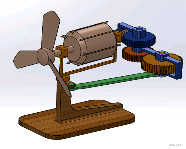
比如自制一个具有扫风功能的小风扇,由于风扇自身尺寸偏小,使用如图1所示传统的复杂机械结还构去实现扫风功能偏难,反而会影响风扇的运行效果和产生噪音。
还比如用超声波制作一个类似于雷达扫描的装置感知周围环境轮廓,需要使用某种旋转机构驱动超声波探头匀速旋转固定角度。
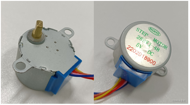
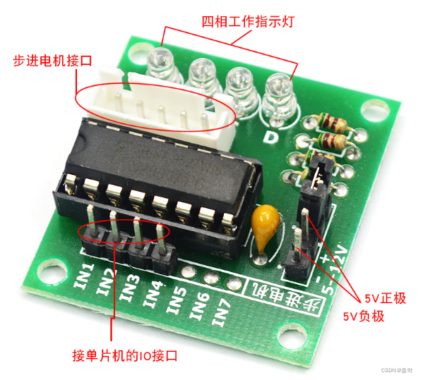
针对以上需求,有两种解决方案,一种是选择扭力合适的舵机,另一种就是选用如图2所示的4相5线步进电机,其型号为28BYJ-48,驱动电压为5V,需要使用ULN2003驱动板进行驱动,如图3所示。
下面就具体介绍如何使用STM32单片机驱动它转动固定角度吧,亲测有效好用。
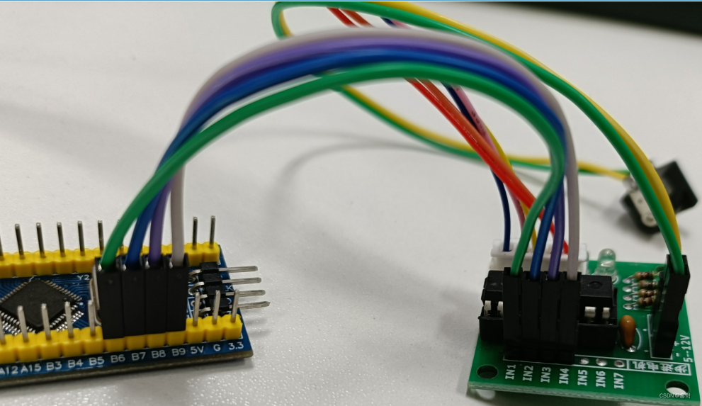
一、STM32和ULN2003驱动板接线
| STM32F103C8T6 | ULN2003驱动板 |
| PB6 | IN1 |
| PB7 | IN2 |
| PB8 | IN3 |
| PB9 | IN4 |
驱动板供电需单独供电,电压范围5-12V,不建议用单片机进行供电,因为单片机是微控制器,不是驱动器。
然后接线的实物图如图4所示。
二、STM32F103C8T6程序编写
1、在工程里面新建step.h文件,在里面定义电机所用端口
- /* 定义步进电机连接的GPIO端口*/
- #define IN1_PORT GPIOB
- #define IN1_CLK RCC_APB2Periph_GPIOB
- #define IN1_PIN GPIO_Pin_6
-
- #define IN2_PORT GPIOB
- #define IN2_CLK RCC_APB2Periph_GPIOB
- #define IN2_PIN GPIO_Pin_7
-
- #define IN3_PORT GPIOB
- #define IN3_CLK RCC_APB2Periph_GPIOB
- #define IN3_PIN GPIO_Pin_8
-
- #define IN4_PORT GPIOB
- #define IN4_CLK RCC_APB2Periph_GPIOB
- #define IN4_PIN GPIO_Pin_9

2、新建step.c文件,编写step引脚初始化函数:
- void STEP_GPIO_Config(void)
- {
- /*定义一个GPIO_InitTypeDef类型的结构体*/
- GPIO_InitTypeDef GPIO_InitStructure;
-
- /*开启STEP相关的GPIO外设时钟*/
- RCC_APB2PeriphClockCmd( IN1_CLK | IN2_CLK | IN3_CLK | IN4_CLK, ENABLE);
- /*选择要控制STEP的GPIO引脚*/
- GPIO_InitStructure.GPIO_Pin = IN1_PIN;
-
- /*设置引脚模式为通用推挽输出*/
- GPIO_InitStructure.GPIO_Mode = GPIO_Mode_Out_PP;
-
- /*设置引脚速率为50MHz */
- GPIO_InitStructure.GPIO_Speed = GPIO_Speed_50MHz;
-
- /*调用库函数,初始化GPIO*/
- GPIO_Init(IN1_PORT, &GPIO_InitStructure);
-
- GPIO_InitStructure.GPIO_Pin = IN2_PIN;
- GPIO_Init(IN2_PORT, &GPIO_InitStructure);
-
- GPIO_InitStructure.GPIO_Pin = IN3_PIN;
- GPIO_Init(IN3_PORT, &GPIO_InitStructure);
-
- GPIO_InitStructure.GPIO_Pin = IN4_PIN;
- GPIO_Init(IN4_PORT, &GPIO_InitStructure);
-
- /* 初始化电机引脚 */
- GPIO_ResetBits(IN1_PORT, IN1_PIN);
- GPIO_ResetBits(IN2_PORT, IN2_PIN);
- GPIO_ResetBits(IN3_PORT, IN3_PIN);
- GPIO_ResetBits(IN4_PORT, IN4_PIN);
- }
3、编写正反转、停止函数
先定义使电机正反转的编码数组
- unsigned short phasecw[4] ={0x0200,0x0100,0x0080,0x0040};// D-C-B-A 反转
- unsigned short phaseccw[4]={0x0040,0x0080,0x0100,0x0200};// A-B-C-D 正转
然后编写正转、反转、停止函数,里面的SysTick_Delay_Ms(3);函数是在系统时钟配置函数里面编写的进准延时函数,单位是ms,这里使用延时3ms。
- void MotoRccw(void) //正转
- {
- int i;
- for(i=0;i<4;i++)
- {
- GPIO_Write(GPIOB,phaseccw[i]);
- SysTick_Delay_Ms(3);
- }
- }
-
- void MotoRcw(void) //反转
- {
- int i;
- for(i=0;i<4;i++)
- {
- GPIO_Write(GPIOB,phasecw[i]);
- SysTick_Delay_Ms(3);
- }
- }
-
- void MotorStop(void) //停止
- {
- GPIO_Write(GPIOB,0x0000);
- }
4、编写电机正/反转特定角度函数
- //控制电机正转还是反转某个角度
- //direction方向,1为正转,0为反转
- //angle角度,0-360度
- void Motor_Ctrl_Direction_Angle(int direction, int angle)
- {
- u16 j;
- if(direction == 1)
- {
- for(j=0;j<64*angle/45;j++)
- {
- MotoRccw();//正转
- }
- MotorStop();//停止
- }
- else
- {
- for(j=0;j<64*angle/45;j++)
- {
- MotoRcw();//反转
- }
- MotorStop();//停止
- }
- }
最后别忘了将.c文件编写的函数在.h文件里面申明
- void STEP_GPIO_Config(void);
- void MotorStop(void);
- void MotoRccw(void);
- void MotoRcw(void);
- void Motor_Ctrl_Direction_Angle(int direction, int angle);
5、编写主函数程序
通过死循环让电机往复循环转动360度。
- while(1)
- {
- Motor_Ctrl_Direction_Angle(1,360);//正转180度
- SysTick_Delay_Ms(500);
- Motor_Ctrl_Direction_Angle(0,360);//反转90度
- SysTick_Delay_Ms(500);
- }
然后,这样就可以在此基础上修改主程序代码,实现自己想要的效果啦!
完整工程代码连接:https://gitee.com/liangshuzhi/stm32-project-engineering.git
- stm32串口连接esp8266WiFi模块,通过AT指令控制模块进行数据收发,和服务器进行通讯。可以用于单片机直接的通信,手机和单片机通讯等。_基于stm32、esp8266及ov7670的无线图传下位机源码基于stm32、esp8266... [详细]
赞
踩
 使用STM32作为控制器,ULN2003作为驱动模块驱动28BYJ-48步进电机,可实现通过按键控制电机以不同速度转过不同角度……_步进电机uln2003步进电机uln2003本篇文章包含的内容一、步进电机的结构和工作原理1.1步进控制系统... [详细]
赞
踩
 欢迎来到我的博客。今天我想向大家介绍一下STM32软件I2C功能。首先,让我们来了解一下I2C(Inter-IntegratedCircuit)总线。I2C是一种串行通信总线,最初由Philips公司开发。它允许多个设备使用同一条总线进行通... [详细]
赞
踩
- 本篇文章介绍了在STM32平台利用W5500芯片实现以太网通信的原理以及嵌入式代码详解,同时对官方的例程进行了解读,帮助嵌入式工程师熟悉物联网TCP/IP技术。_stm32spi与w5500stm32spi与w5500STM32系列32位微... [详细]
赞
踩
 讲解Python实现串口通信的过程和代码,实现了发送字符串(utf-8)数据和十六进制(hex)数据的串口通信,并且与自制stm32核心板实现了串口通信,并在OLED屏上显示通信数据。文章中有完整项目的下载链接。_python串口通信pyt... [详细]
赞
踩
- Flash:存放代码SRAM:内存外设1、STM32片内自带SRAM和FLASH,FLASH是用来存储程序的,SRAM是用来存储程序运行中的中间变量,通常不同型号的STM32的SRAM和FLASH大小是不相同的FLASH存储器又成为闪存,它... [详细]
赞
踩
- Clion使用笔记(C语言、C++、stm32)_clion配置vs2010工具集clion配置vs2010工具集目录1、Clion安装(以Windows为例)系统要求安装步骤 2、Clion激活(以Windows为例)方法一:j... [详细]
赞
踩
- 作为入门本篇只实现微信小程序接收下位机上传的数据,之后会持续发布如下项目:①可以实现微信小程序控制下位机动作,真正意义上的智能家居;②将网络通讯协议换成MQTT协议再实现上述功能,此时的服务器也不再是ONENET,可以是公用的MQTT服务器... [详细]
赞
踩
- 需要根据硬件工程师设计的电路来规划需要用到的单片机外设,然后对比你选择的单片机资源是否满足,比如时钟频率,Flash,RAM,SPI,IIC,USART,PWM,ADC等等。STM32单片机配备了多种调试和测试接口,如SWD和JTAG接口,... [详细]
赞
踩
- Hi,大家好,这里是丹成学长,今天向大家介绍一个学长做的单片机项目教程:MPU6050姿态解算大家可用于课程设计或毕业设计单片机-嵌入式毕设选题大全及项目分享:https://blog.csdn.net/m0_71572576/articl... [详细]
赞
踩
- 文章目录1,理论分析1.1MPU60501.2Mahony算法原理2,代码实现1.1MPU6050初始化及数据读取1.2Mahony算法c语言实现1.3将代码移植到你的工程3,补充1,理论分析1.1MPU6050MPU6050是一个集成了陀... [详细]
赞
踩
 链接:https://pan.baidu.com/s/15sUFn2t7EzH-gHBsEo-WWw?此工程是基于江科大源码的基础上创作,因为pm2.5这个模块比较冷门,参考的代码比较少,所以开源给大家学习参考!_gp2y1014stm32... [详细]
赞
踩
- 目的:一种廉价的跟随方案,让大家都能够参与进来,技术难度不大,一些人也能够DIY一些属于自己的“跟随”机器人!并不是要做工业应用什么的。只是做出来玩玩~/1/介绍先看视频,视频中是一个简单的4轮模型的小型机器人,做了一个简单的应用(智能行李... [详细]
赞
踩
- 本文介绍通过STM32F103C8T6单片机对HC-SR04测距模块进行驱动,并且通过串口对数据进行打印。_hcsr04stm32自动跟随hcsr04stm32自动跟随1、简介本文介绍通过STM32F103C8T6单片机对HC-SR04测距... [详细]
赞
踩
- 这个项目的硬件端是基于STM32与ESP32开发的,可以获取图像并传输到APP端,控制小车的转速使用PWM的方式,获取周围的环境数据,实现手动控制以及自动避障功能。这个项目中的APP端则可以接收图像信息并显示到APP端上,展示小车的基本信息... [详细]
赞
踩
- 【DIY】STM32、ESP32CAM阿里云小程序监控3D打印智能履带小车_单片机智能小车如何3d打印单片机智能小车如何3d打印1.效果展示(必看!【DIY】STM32、ESP32CAM阿里云小程序监控3D打印智能履带小车//2.APP//... [详细]
赞
踩
- 必须是在具有惯性的系统中,可以通过对一系列脉冲的宽度进行调制,来等效地获得所需要的模拟参量,常应用于电机控速等领域频率=1/TS占空比=TON/TS分辨率=占空比变化步距(PWM的频率在几千到几十KHZ就已经很快了)(分辨率表示占空比的精细... [详细]
赞
踩
- E18-D80NK红外避障传感器介绍,并有STM32使用代码STM32E18-D80NK红外避障传感器E18-D80NK-N是一款红外光电传感器,它同时具备发射和接收功能。通过对发射光进行调制后发出,并通过接收头对反射光进行解调输出。E18... [详细]
赞
踩
- STM32简介点亮PC13LEDGPIOLED闪烁LED流水灯按键控制LED光敏传感器控制蜂鸣器OLED调试工具OLED显示EXTI外部中断对射式红外传感器计次旋转编码器计次STM321-5目录STM32简介点亮PC13LED G... [详细]
赞
踩
- article
STM32 ------ 智能小车(串口-----蓝牙、wifi、4g 循迹------pwm调速、避障-----超声波 舵机、跟随、测速并显示在OLED上、语音小车)_智能小车可以接收外部串口信号操作吗
测速模块周长知道有20格子每个电平转变一次就是1cm用中断计数配置定时器中断1s产生中断计算出中断count++的值除以时间1s====速度。PWM调速小车开启定时器配置时间、模式注意有效电平是高低电平、则车子另一个轮电平要相反才能驱动。摇... [详细]赞
踩

