- 1opencv 图像识别
- 2Speech Emotion Recognition with Multi-task Learning(2021)_speechformer
- 3android四则运算,Android开发之简单的四则运算器的…
- 4【Kotlin基础系列】第6章 包与导入_kotlin import
- 5Mac上配置 Android 环境变量_mac android环境变量配置
- 6mix2s适配鸿蒙,小米MIX2S|MIUI10|9.05.12|GPU调节|CPU调节_最新最全的小米MIX 2SROM刷机包下载、刷机...
- 7使用IDEA创建Maven项目(简单的spring与mybatis整合)_在idea中使用maven做为项目构建工具基于spring boot + mybatis 在idea
- 8位扩展与位截断(四)
- 9HarmonyOS IoT首著,走进万物互联的世界!_书书指 )社交通讯榜第2名 harmonyos
- 10AI短视频制作一本通:文本生成视频、图片生成视频、视频生成视频_ai将图像或文本变成影片
华为配置OSPF的Stub区域示例
赞
踩
配置OSPF的Stub区域示例
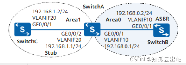
组网图形
- Stub区域简介
- 配置注意事项
- 组网需求
- 配置思路
- 操作步骤
- 配置文件
Stub区域简介
Stub区域的ABR不传播它们接收到的自治系统外部路由,在Stub区域中路由器的路由表规模以及路由信息传递的数量都会大大减少。为保证到自治系统外的路由依旧可达,该区域的ABR将生成一条缺省路由,并发布给Stub区域中的其他非ABR路由器。
例如H公司有一台设备通过单链路与骨干区域连接,这台设备的性能较低,路由表规格也比较小。对于这台设备来说,这个区域需要访问其他区域,或者是OSPF域外的网段的时候,它的路由的下一跳都是这个单链路所对应的下一跳核心设备的IP。所以这个区域没有必要学习到大量的OSPF外部路由,此时就可以考虑将该区域配置成Stub区域。这样就能减小这个区域的路由表规模,降低对设备性能资源的消耗。
配置注意事项
- 骨干区域不能配置成Stub区域。
- Stub区域内不能存在ASBR,即自治系统外部的路由不能在本区域内传播。
- 虚连接不能穿过Stub区域。
- 如果要将一个区域配置成Stub区域,则该区域中的所有路由器都要配置Stub区域属性。
- 如果要将一个区域配置成Totally Stub区域,该区域中的所有路由器必须配置stub命令,而其中该区域的ABR路由器需要配置stub no-summary命令。
- stub no-summary命令仅能用于ABR上,用于禁止ABR向Stub区域内发布3类LSA。在ABR上配置该命令以后该区域成为Totally Stub区域,这时区域内的路由表项进一步减少,只有区域内路由和ABR通告的一条缺省路由。
- 本举例适用的产品包括:
- V200R011C10及之后版本的S2720-EI
- S3700-EI、S3700-HI
- S5700-EI、S5700-HI、S5710-EI、S5710-HI、S5720-LI、S5720S-LI、S5720-SI、S5720S-SI、S5720I-SI、S5720-EI、S5720-HI、S5730-HI、S5730-SI、S5730S-EI、S5731-H、S5731-S、S5731S-S、S5731S-H、S5731-H-K、S5732-H、S5732-H-K、S2730S-S、S5735-L-I、S5735-L1、S300、S5735-L、S5735S-L1、S5735S-L、S5735S-L-M、S500、S5735-S、S5735S-S、S5735-S-I、S5735S-H、S5736-S
- S6700-EI、S6720-LI、S6720S-LI、S6720-SI、S6720S-SI、S6720-EI、S6720S-EI、S6720-HI、S6730-H、S6730-S、S6730S-S、S6730S-H、S6730-H-K
- S7703、S7706、S7712、S7710、S7703 PoE、S7706 PoE、S7905、S7908
- S9703、S9706、S9712
-
本举例中产品的默认适用版本请参见“案例适用的产品和版本说明”中的表1。
如需了解交换机软件配套详细信息,请点击Info-Finder,在选择产品系列或产品型号后,在“硬件中心”进行查询。
S5731-L和S5731S-L属于远端模块,不支持Web管理、YANG和命令行,仅支持通过中心交换机对其下发配置,相关操作请参见《S300, S500, S2700, S5700, S6700 V200R022C00 配置指南-设备管理》中的“智能极简园区网络配置(小行星方案)”。
组网需求
如图1所示,三台交换机之间运行OSPF协议,整个OSPF网络被划分为Area0和Area1两个区域,其中SwitchB作为ASBR与OSPF外部网络实现互通。现要求在不影响通信的情况下减少SwitchC上OSPF路由表的规模。
配置思路
采用如下的思路配置OSPF Stub区域:
-
在各交换机上配置OSPF基本功能,实现OSPF网络的基本互通。
-
在SwitchB上配置静态路由,并引入到OSPF路由表中,实现OSPF网络到外部网络路由可达。
-
配置Area1为Stub区域,初步减少SwitchC上OSPF路由表的规模。
-
在Area1的ABR(SwitchA)上配置禁止向Stub区域通告Type3 LSA,即将Area1配置为Totally Stub区域,达到最大限度减少SwitchC上OSPF路由表规模的目的。
操作步骤
- 配置各接口所属的VLAN
- # 配置SwitchA。SwitchB和SwitchC的配置与SwitchA类似。
- <HUAWEI> system-view
- [HUAWEI] sysname SwitchA
- [SwitchA] vlan batch 10 20
- [SwitchA] interface gigabitethernet 0/0/1
- [SwitchA-GigabitEthernet0/0/1] port link-type trunk
- [SwitchA-GigabitEthernet0/0/1] port trunk allow-pass vlan 10
- [SwitchA-GigabitEthernet0/0/1] quit
- [SwitchA] interface gigabitethernet 0/0/2
- [SwitchA-GigabitEthernet0/0/2] port link-type trunk
- [SwitchA-GigabitEthernet0/0/2] port trunk allow-pass vlan 20
- [SwitchA-GigabitEthernet0/0/2] quit
- 配置各VLANIF接口的IP地址
- # 配置SwitchA。SwitchB和SwitchC的配置与SwitchA类似。
- [SwitchA] interface vlanif 10
- [SwitchA-Vlanif10] ip address 192.168.0.1 24
- [SwitchA-Vlanif10] quit
- [SwitchA] interface vlanif 20
- [SwitchA-Vlanif20] ip address 192.168.1.1 24
- [SwitchA-Vlanif20] quit
- 配置OSPF基本功能
- # 配置SwitchA。
- [SwitchA] ospf 1 router-id 10.1.1.1
- [SwitchA-ospf-1] area 0
- [SwitchA-ospf-1-area-0.0.0.0] network 192.168.0.0 0.0.0.255
- [SwitchA-ospf-1-area-0.0.0.0] quit
- [SwitchA-ospf-1] area 1
- [SwitchA-ospf-1-area-0.0.0.1] network 192.168.1.0 0.0.0.255
- [SwitchA-ospf-1-area-0.0.0.1] quit
- [SwitchA-ospf-1] quit
- # 配置SwitchB。
- [SwitchB] ospf 1 router-id 10.2.2.2
- [SwitchB-ospf-1] area 0
- [SwitchB-ospf-1-area-0.0.0.0] network 192.168.0.0 0.0.0.255
- [SwitchB-ospf-1-area-0.0.0.0] quit
- [SwitchB-ospf-1] quit
- # 配置SwitchC。
- [SwitchC] ospf 1 router-id 10.3.3.3
- [SwitchC-ospf-1] area 1
- [SwitchC-ospf-1-area-0.0.0.1] network 192.168.1.0 0.0.0.255
- [SwitchC-ospf-1-area-0.0.0.1] quit
- [SwitchC-ospf-1] quit

- 配置SwitchB引入静态路由
- [SwitchB] ip route-static 10.0.0.0 8 null 0
- [SwitchB] ospf 1
- [SwitchB-ospf-1] import-route static type 1 //SwitchB作为ASBR,引入外部路由
- [SwitchB-ospf-1] quit
- # 查看SwitchC的OSPF路由表信息,可以看到OSPF路由表中存在AS外部的路由。
- [SwitchC] display ospf routing
- OSPF Process 1 with Router ID 10.3.3.3
- Routing Tables
- Routing for Network
- Destination Cost Type NextHop AdvRouter Area
- 192.168.1.0/24 1 Transit 192.168.1.2 10.3.3.3 0.0.0.1
- 192.168.0.0/24 2 Inter-area 192.168.1.1 10.1.1.1 0.0.0.1
- Routing for ASEs
- Destination Cost Type Tag NextHop AdvRouter
- 10.0.0.0/8 3 Type1 1 192.168.1.1 10.2.2.2
- Total Nets: 3
- Intra Area: 1 Inter Area: 1 ASE: 1 NSSA: 0

- 配置Area1为Stub区域
- # 配置SwitchA。
- [SwitchA] ospf 1
- [SwitchA-ospf-1] area 1
- [SwitchA-ospf-1-area-0.0.0.1] stub //配置area 1区域为stub区域,area 1内的所有路由器都要配置stub命令
- [SwitchA-ospf-1-area-0.0.0.1] quit
- [SwitchA-ospf-1] quit
- # 配置SwitchC。
- [SwitchC] ospf 1
- [SwitchC-ospf-1] area 1
- [SwitchC-ospf-1-area-0.0.0.1] stub //配置area 1区域为stub区域,area 1内的所有路由器都要配置stub命令
- [SwitchC-ospf-1-area-0.0.0.1] quit
- [SwitchC-ospf-1] quit
- # 查看SwitchC的OSPF路由表信息,发现此时AS外部的路由10.0.0.0/8已经消失,但是多了一条通往区域外部的缺省路由。
- [SwitchC] display ospf routing
- OSPF Process 1 with Router ID 10.3.3.3
- Routing Tables
- Routing for Network
- Destination Cost Type NextHop AdvRouter Area
- 192.168.1.0/24 1 Transit 192.168.1.2 10.3.3.3 0.0.0.1
- 0.0.0.0/0 2 Inter-area 192.168.1.1 10.1.1.1 0.0.0.1
- 192.168.0.0/24 2 Inter-area 192.168.1.1 10.1.1.1 0.0.0.1
- Total Nets: 3
- Intra Area: 1 Inter Area: 2 ASE: 0 NSSA: 0

- 配置Area1为Totally Stub区域
- [SwitchA] ospf 1
- [SwitchA-ospf-1] area 1
- [SwitchA-ospf-1-area-0.0.0.1] stub no-summary //配置area 1区域为Totally Stub区域,area 1内的ABR要配置stub no-summary命令,其他设备配置stub命令
- [SwitchA-ospf-1-area-0.0.0.1] quit
- [SwitchA-ospf-1] quit
- 验证配置结果
- # 查看SwitchC的OSPF路由表,发现目的地址为192.168.0.0/24的区域间路由也消失了,仅保留了区域内的OSPF路由以及一条通往区域外部缺省路由。
- [SwitchC] display ospf routing
- OSPF Process 1 with Router ID 10.3.3.3
- Routing Tables
- Routing for Network
- Destination Cost Type NextHop AdvRouter Area
- 192.168.1.0/24 1 Transit 192.168.1.2 10.3.3.3 0.0.0.1
- 0.0.0.0/0 2 Inter-area 192.168.1.1 10.1.1.1 0.0.0.1
- Total Nets: 2
- Intra Area: 1 Inter Area: 1 ASE: 0 NSSA: 0
配置文件
-
- SwitchA的配置文件
- #
- sysname SwitchA
- #
- vlan batch 10 20
- #
- interface Vlanif10
- ip address 192.168.0.1 255.255.255.0
- #
- interface Vlanif20
- ip address 192.168.1.1 255.255.255.0
- #
- interface GigabitEthernet0/0/1
- port link-type trunk
- port trunk allow-pass vlan 10
- #
- interface GigabitEthernet0/0/2
- port link-type trunk
- port trunk allow-pass vlan 20
- #
- ospf 1 router-id 10.1.1.1
- area 0.0.0.0
- network 192.168.0.0 0.0.0.255
- area 0.0.0.1
- network 192.168.1.0 0.0.0.255
- stub no-summary
- #
- return
- SwitchB的配置文件
- #
- sysname SwitchB
- #
- vlan batch 10
- #
- interface Vlanif10
- ip address 192.168.0.2 255.255.255.0
- #
- interface GigabitEthernet0/0/1
- port link-type trunk
- port trunk allow-pass vlan 10
- #
- ospf 1 router-id 10.2.2.2
- import-route static type 1
- area 0.0.0.0
- network 192.168.0.0 0.0.0.255
- #
- ip route-static 10.0.0.0 255.0.0.0 NULL0
- #
- return
- SwitchC的配置文件
- #
- sysname SwitchC
- #
- vlan batch 20
- #
- interface Vlanif20
- ip address 192.168.1.2 255.255.255.0
- #
- interface GigabitEthernet0/0/1
- port link-type trunk
- port trunk allow-pass vlan 20
- #
- ospf 1 router-id 10.3.3.3
- area 0.0.0.1
- network 192.168.1.0 0.0.0.255
- stub
- #
- return


