
- 1Transformer大模型实战 了解BART模型
- 2SCA算法在23个常用基准测试函数上的运行效果及MATLAB代码分析_测试函数matlab
- 3计算机组成原理实验报告1 | 实验1.1 运算器实验(键盘方式)_计算机组成原理运算器实验报告
- 4Postman文件数据导入导出_postman 导入
- 5深信服安全软件产品配置概况_深信服 安装了几个软件
- 6filebeat_filebeat 启动
- 7UML—用例图_uml事件流
- 8Hive常见的面试题(十二道)_hive面试常问问题
- 9解决 Element-UI 的 el-dialog 对话框移动问题的方法_el-dialog draggable 无效
- 10网络是怎样连接的-小笔记
树莓派pico移植QP/C状态机架构_qpc 状态机
赞
踩
前言
此文章使用的硬件是树莓派pico开发板,软件架构是QP/C状态机架构,使用C作为开发语言。目标是将QP架构中的QV内核移植到树莓派pico开发板中,实现Led定时闪烁功能。(文字较多,耐心阅读)
1. QP/C架构
QP/C 实时嵌入式框架 (RTEF) 是专为实时嵌入式 (RTE) 系统量身定制的主动对象计算模型的轻量级实现。
QP既是用于构建由活动对象组成的QP/C应用程序的软件基础设施,也是用于以确定性方式执行活动对象的运行时环境。QP/C 框架还支持分层状态机,用于指定活动对象的行为 。QP/C 框架可以被看作是一个真正的事件驱动的“反应式”实时操作系统 (RTOS)。
QP/C实时嵌入式架构的开发软件是QM™ Model-Based Design Tool,QM™ (QP Modeler) 是一款免费的基于模型的设计 (MBD) 和自动代码生成工具,用于设计基于有限状态机(UML 状态图)和 QP™ 框架的软件,可以通过图形界面生成Hsm( Hierarchical State Machines)状态机。


2. 树莓派pico开发板
Raspberry Pi Pico 是树莓派基金会发布了首款微控制器级产品。基于 RP2040 芯片构建。

RP2040 芯片是 7×7mm QFN-56 封装的,具体规格参数如下:
– 双核 Arm Cortex-M0 + @ 133MHz
– 芯片内置 264KB SRAM 和 2MB 的板载闪存
– 通过专用 QSPI 总线支持最高 16MB 的片外闪存
– DMA 控制器
– 30 个 GPIO 引脚,其中 4 个可用作模拟输入
– 2 个 UART、2 个 SPI 控制器和 2 个 I2C 控制器
– 16 个 PWM 通道
– USB 1.1 主机和设备支持
– 8 个树莓派可编程 I/O(PIO)状态机,用于自定义外围设备支持
– 支持 UF2 的 USB 大容量存储启动模式,用于拖放式编程。
硬件是从淘宝 微雪电子购买,虽然比别的店铺贵点,但是此店铺售后确实给力,几块钱能买一个一对一的技术指导,不亏。
3. QP/C架构移植
Quantum Leaps官方提供了例程,但是例程基本都是基于ST32微控制器和keil 的开发例程,但是树莓派pico的控制器是RP2040,BSP这部分代码与例程不一致,并且使用GUN编译器,需要用户自己编写构建系统。
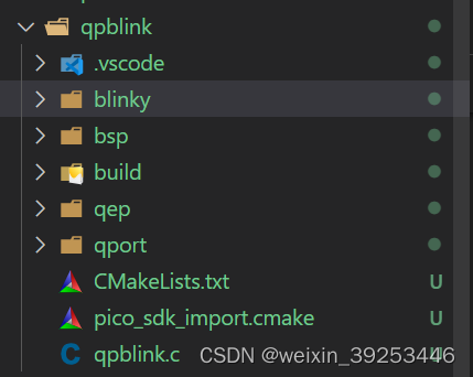
树莓派pico移植QP/C架构分为QP/C源代码移植、树莓派pico BSP部分移植、cmake文件编写。
3.1 准备QP/C架构代码
这部分主要包括准备QP架构源代码移植和有关Cortex-M0 + 接口部分代码。
3.1.1QP架构源码
从Quantum Leaps官网下载软件安装后,在安装目录\qp\qpc下面有include和src目录,这两个目录存放的是QP架构的头文件和源代码。

3.1.2 Cortex-M0 + port文件
树莓派pico 开发板使用的RP2040微控制器是基于Arm Cortex-M0 +内核,需要准备针对该内核的接口文件。port文件再qp\qpc\ports\arm-cm\qv\gnu目录下,文件如下:

3.1.3 qm官方示例代码
准备blink示例代码,代码目录在qp\qpc\examples\arm-cm\blinky_nucleo-c031c6\qv目录下,需要准备的文件是bsp.c和qp\qpc\examples\arm-cm\blinky_nucleo-c031c6目录下的blinky.c、blink.h、bsp.h、main.c文件

3.2 创建pico项目
- 树莓派官方为树莓派pico提供了基于C语言的SDK,方便新项目开发。pico新项目可以通过Python脚本创建,执行脚本后界面如下:

点击“OK”后,会自动生成一个main.c、CMakeLists.txt文件,这几个文件是架构移植的基本文件。
- 复制QP/C架构源代码和port项目代码到项目目录下面,qep文件夹存放的是QP/C架构相关代码,qport存放的是有关m0+控制器文件
- 复制例程代码到工程目录blinky、bsp目录下
3.3 修改代码
- 将QP官方例程mian.c内如复制到工程目录qpblink.c中
int main() {
    stdio_init_all();
    sleep_ms(10000);
    printf("pico stdio init all\n");
    add_repeating_timer_ms(10, repeating_timer_callback, NULL, &timer);
    //以下内容是官方例程main.c中文件
    QF_init();
    printf("qf init\n");      // initialize the framework and the underlying RT kernel
    BSP_init();
    printf("BSP init\n");                    // initialize the BSP
    BSP_start();     // start the AOs/Threads

    return QF_run(); // run the QF application
}
- 1
- 2
- 3
- 4
- 5
- 6
- 7
- 8
- 9
- 10
- 11
- 12
- 13
- 14
- 修改例程bsp.c文件
将bsp中关于STM32控制器硬件控制相关代码删除;
void BSP_init(void) {

    printf("bsp init ... ...\n");
}
- 1
- 2
- 3
- 4
为了方便演示将ledOn和ledOff修改为打印信息
void BSP_ledOn() {
    // GPIOA->BSRR = (1U << LD4_PIN);  // turn LED on
    printf("led on ... ...\n");
}
//............................................................................
void BSP_ledOff() {
    // GPIOA->BSRR = (1U << (LD4_PIN + 16U));  // turn LED off
    printf("led off ... ...\n");
}
- 1
- 2
- 3
- 4
- 5
- 6
- 7
- 8
- 9
- QF回调函数修改
这里将回调函数内部关于stm32控制器内容删除。
void QF_onStartup(void) {


#ifdef Q_SPY
    NVIC_EnableIRQ(USART2_IRQn); // UART2 interrupt used for QS-RX
#endif
}
//............................................................................
void QF_onCleanup(void) {
}
//............................................................................
void QV_onIdle(void) { // called with interrupts DISABLED, see NOTE01

    // toggle an LED on and then off (not enough LEDs, see NOTE02)
    //GPIOA->BSRR = (1U << LD4_PIN);         // turn LED[n] on
    //GPIOA->BSRR = (1U << (LD4_PIN + 16U)); // turn LED[n] off

#ifdef Q_SPY
#elif defined NDEBUG
    // Put the CPU and peripherals to the low-power mode.
    // you might need to customize the clock management for your application,
    // see the datasheet for your particular Cortex-M MCU.
    //
    // !!!CAUTION!!!
    // QV_CPU_SLEEP() contains the WFI instruction, which stops the CPU
    // clock, which unfortunately disables the JTAG port, so the ST-Link
    // debugger can no longer connect to the board. For that reason, the call
    // to QV_CPU_SLEEP() has to be used with CAUTION.
    //
    // NOTE: If you find your board "frozen" like this, strap BOOT0 to VDD and
    // reset the board, then connect with ST-Link Utilities and erase the part.
    // The trick with BOOT(0) is it gets the part to run the System Loader
    // instead of your broken code. When done disconnect BOOT0, and start over.
    //
    //QV_CPU_SLEEP();  // atomically go to sleep and enable interrupts
    QF_INT_ENABLE(); // for now, just enable interrupts
#else
    QF_INT_ENABLE(); // just enable interrupts
#endif
}
- 1
- 2
- 3
- 4
- 5
- 6
- 7
- 8
- 9
- 10
- 11
- 12
- 13
- 14
- 15
- 16
- 17
- 18
- 19
- 20
- 21
- 22
- 23
- 24
- 25
- 26
- 27
- 28
- 29
- 30
- 31
- 32
- 33
- 34
- 35
- 36
- 37
- 38
- 39
- 40
- QP系统时钟节拍
官方给的例程中有关系统时钟节拍放在系统滴答定时中断函数中,如下所示:
void SysTick_Handler(void) {
    QTIMEEVT_TICK_X(0U, &l_SysTick_Handler); // time events at rate 0
    QV_ARM_ERRATUM_838869();
}
- 1
- 2
- 3
- 4
但是树莓派pico中暂时没找到系统滴答时钟中断入口函数,所以采用定时器中断来产生系统时钟节拍,代码如下:
struct repeating_timer timer;

bool repeating_timer_callback(struct repeating_timer *t) {
    QTIMEEVT_TICK_X(0U, &l_SysTick_Handler); // time events at rate 0
    QV_ARM_ERRATUM_838869();
    return true;
}
- 1
- 2
- 3
- 4
- 5
- 6
- 7
以上需要移植的代码已经修改完成。
3.4 cmake 构建系统
移植好代码后,需要将编写CmakeLists.txt,编译工程。
在这个移植工程中,每个文件夹作为一个接口库,最终编译到工程文件中,工程主CmakeLists.txt如下所示:
# Generated Cmake Pico project file

cmake_minimum_required(VERSION 3.13)

set(CMAKE_C_STANDARD 11)
set(CMAKE_CXX_STANDARD 17)

# Initialise pico_sdk from installed location
# (note this can come from environment, CMake cache etc)
set(PICO_SDK_PATH "/home/pi/pico/pico-sdk")

set(PICO_BOARD pico CACHE STRING "Board type")

# Pull in Raspberry Pi Pico SDK (must be before project)
include(pico_sdk_import.cmake)

if (PICO_SDK_VERSION_STRING VERSION_LESS "1.4.0")
  message(FATAL_ERROR "Raspberry Pi Pico SDK version 1.4.0 (or later) required. Your version is ${PICO_SDK_VERSION_STRING}")
endif()

project(qpblink C CXX ASM)

# Initialise the Raspberry Pi Pico SDK
pico_sdk_init()

# Add executable. Default name is the project name, version 0.1

add_executable(qpblink qpblink.c )

pico_set_program_name(qpblink "qpblink")
pico_set_program_version(qpblink "0.1")

pico_enable_stdio_uart(qpblink 1)
pico_enable_stdio_usb(qpblink 1)

add_subdirectory(qep)
add_subdirectory(qport)
add_subdirectory(blinky)
add_subdirectory(bsp)


# Add the standard library to the build
target_link_libraries(qpblink
        pico_stdlib
        libblinky
        qep_fram
        libbsp
        qeport)

# # Add the standard include files to the build
# target_include_directories(qpblink PRIVATE
#   ${CMAKE_CURRENT_LIST_DIR}
#   ${CMAKE_CURRENT_LIST_DIR}/.. # for our common lwipopts or any other standard includes, if required
# )

# # Add any user requested libraries
# target_link_libraries(qpblink
#         )

pico_add_extra_outputs(qpblink)
- 1
- 2
- 3
- 4
- 5
- 6
- 7
- 8
- 9
- 10
- 11
- 12
- 13
- 14
- 15
- 16
- 17
- 18
- 19
- 20
- 21
- 22
- 23
- 24
- 25
- 26
- 27
- 28
- 29
- 30
- 31
- 32
- 33
- 34
- 35
- 36
- 37
- 38
- 39
- 40
- 41
- 42
- 43
- 44
- 45
- 46
- 47
- 48
- 49
- 50
- 51
- 52
- 53
- 54
- 55
- 56
- 57
- 58
- 59
- 60
3.5 测试
将编译好.uf2文件下载到树莓派pico中,在串口调试助手或者PuTTY中打印信息如下:
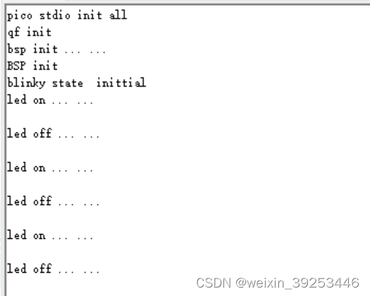
在串口助手中交替打印出 led变化信息。
4. 总结
从打印结构看,此次移植是成功的,QV内核已经在树莓派pico上运行起来。有关QP/C 实时嵌入式框架更深入的功能继续研究。
这篇文章写的还是有些杂乱,后续会提高写作水平。感谢各位读者,共勉。


