- 1unity 录制360全景渲染图_unity 360录屏 地形渲染不出来
- 2docker-compose部署nextcloud教程_censtos怎么用docker安装nextcloud详细操作
- 3Python基础教程(第三版)读书笔记(3)
- 4HDFS 底层交互原理解析_文件同步到hdfs的底层逻辑
- 5Vue为axios设置请求拦截器(全局配置Authorization携带token)_axios request authorization
- 6【无人机三维路径规划】基于人工蜂群算法ABC实现无人机复杂地形三维航迹避障规划附Matlab代码_三维路径规划避障算法
- 7内网穿透工具总结_secure socket funneling执行命令
- 8院士交锋,专家论道|NLP大模型技术与应用十大挑战,剑指AI未来_黄松芳 大模型
- 9力扣---戳气球_力扣戳气球
- 10python为什么被称为胶水语言_为什么说python是胶水语言
基于eNSP的校园网规划与设计_ensp校园网络毕业设计
赞
踩
一、实验设计背景
校园网规划设计的背景需求主要是为了满足用户、应用、技术和管理等方面的需求,提高校园网的性能和服务质量,为高校信息化建设提供更好的支持和保障。
二、总体网络拓扑设计
本次的校园网规划与设计主要建设有线与无线结合,无线方面采用三层旁挂的AC+Fit AP的组网模式。
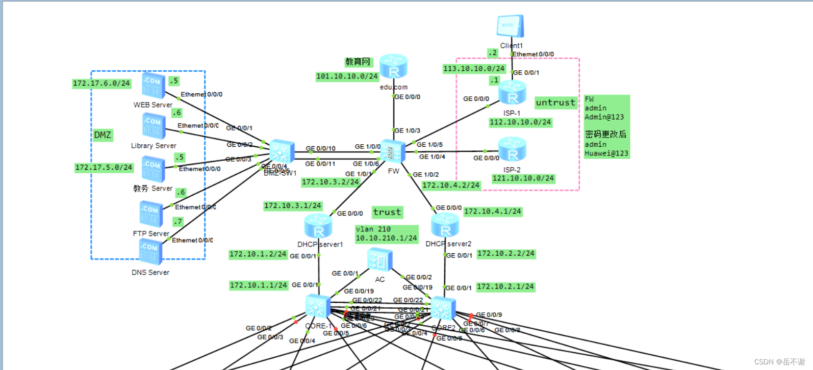
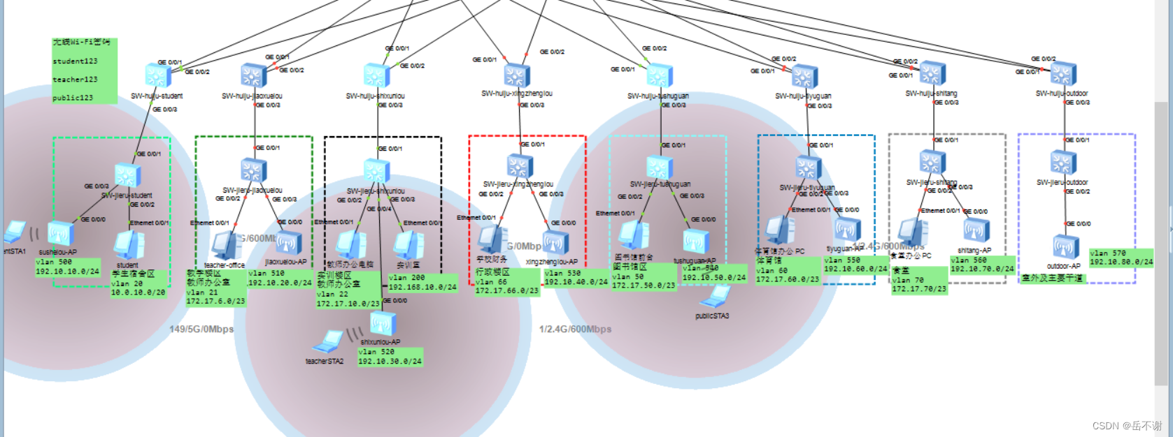
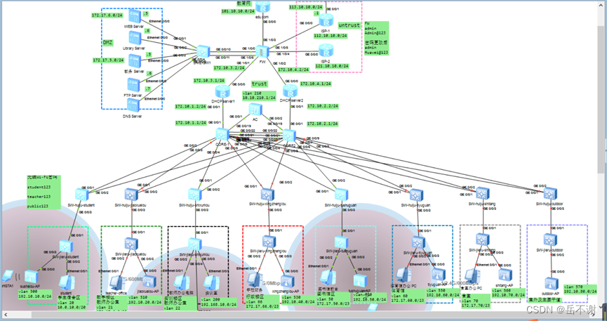
三、网络基础配置规划
3.1 VLAN/IP的规划设计
表3-1 区域的VLAN与IP规划
| 区域 | VLAN | 网段与子网掩码 | 网关 |
| 学生宿舍 | 20 | 10.0.10.0/20 | 10.0.10.1 |
| 教学楼 | 21 | 172.17.6.0/23 | 172.17.6.1 |
| 实训楼 | 22 | 172.17.10.0/23 | 172.17.10.1 |
| 实训室 | 200 | 192.168.10.0/24 | 192.168.10.1 |
| 行政楼 | 66 | 172.17.66.0/23 | 172.17.66.1 |
| 图书馆 | 50 | 172.17.50.0/23 | 172.17.50.1 |
| 体育馆 | 60 | 172.17.60.0/23 | 172.17.60.1 |
| 食堂 | 70 | 172.17.70.0/23 | 172.17.70.1 |
表3-2 DMZ区IP规划
| 服务器 | 网段与子网掩码 | 网关 |
| WEB Server | 172.17.6.5/24 | 172.17.6.1 |
| Library Server | 172.17.6.6/24 | 172.17.6.1 |
| 教务Server | 172.17.5.5/24 | 172.17.5.1 |
| FTP Server | 172.17.5.6/24 | 172.17.5.1 |
| DNS Server | 172.17.5.7/24 | 172.17.5.1 |
| … | … | … |
3.2 CORE-DHCP server-FW的端口配置
表3-3 CORE-DHCP server-FW的端口配置
| 设备 | 端口 | IP |
| FW | GE 1/0/1 | 172.10.3.2/24 |
| FW | GE 1/0/2 | 172.10.4.2/24 |
| DHCP server1 | GE 0/0/0 | 172.10.3.1/24 |
| DHCP server1 | GE 0/0/1 | 172.10.1.2/24 |
| DHCP server2 | GE 0/0/0 | 172.10.4.1/24 |
| DHCP server2 | GE 0/0/1 | 172.10.2.2/24 |
| CORE-1 | GE 0/0/1 | 172.10.1.1/24(vlan2) |
| CORE-2 | GE 0/0/1 | 172.10.2.1/24(vlan2) |
3.3 WLAN的规划与设计
表3-4 WLAN规划
| 配置项 | 学生 | 老师 | 公用Wi-Fi/来宾 |
| STA业务VLAN | VLAN202 | VLAN203 | VLAN204 |
| IP地址段 | 10.202.1.0 | 10.203.1.0 | 10.204.1.0 |
| 子网掩码 | 255.255.128.0(17) | 255.255.224.0(19) | 255.255.224.0(19) |
| 网关 | 10.202.1.1 | 10.203.1.1 | 10.204.1.1 |
| DHCP服务器 | 为AP和STA分配地址 | ||
| AC的源接口IP地址 | VLANIF210:10.10.210.1/24 | ||
| AP组 | 根据楼栋设置AP组 | ||
| 域管理模板 | 名称:China 国家码:CN | ||
| SSID模板 | 名称:student-Wi-Fi SSID名称: student-Wi-Fi | 名称:teacher-Wi-Fi SSID名称: student-Wi-Fi | 名称:public-Wi-Fi SSID名称: public-Wi-Fi |
| 安全模板 | 名称:student-Wi-Fi 安全策略: WPA2+PSK+AES 密码:student123 | 名称:teacher-Wi-Fi 安全策略: WPA2+PSK+AES 密码:teacher123 | 名称:public-Wi-Fi 安全策略: WPA2+PSK+AES 密码: public123 |
| VAP模板 | 名称:student-Wi-Fi转发模式:直接转发 业务VLAN:202 引用模板: SSID模板: student-Wi-Fi 安全模板: student-Wi-Fi | 名称:teacher-Wi-Fi 转发模式:直接转发 业务VLAN:203 引用模板: SSID模板: teacher-Wi-Fi 安全模板: teacher-Wi-Fi | 名称:public-Wi-Fi 转发模式:直接转发 业务VLAN:204 引用模板: SSID模板: public-Wi-Fi 安全模板: public-Wi-Fi |
表3-5 管理AP地址的规划
| AP安装位置 | VLAN | 网段/子网掩码 | 网关 |
| 学生宿舍楼 | 500 | 192.10.10.0/24 | 192.10.10.1 |
| … | … | … | … |
| 教学楼 | 510 | 192.10.20.0/24 | 192.10.20.1 |
| … | … | … | … |
| 实训楼 | 520 | 192.10.30.0/24 | 192.10.30.1 |
| … | … | … | … |
| 行政楼 | 530 | 192.10.40.0/24 | 192.10.40.1 |
| 图书馆 | 540 | 192.10.50.0/24 | 192.10.50.1 |
| 体育馆 | 550 | 192.10.60.0/24 | 192.10.60.1 |
| 食堂 | 560 | 192.10.70.0/24 | 192.10.70.1 |
| … | … | … | … |
| 室外场所/主要干道 | 570 | 192.10.80.0/24 | 192.10.80.1 |
3.4 DMZ、edu_zone和ISP接入到防火墙的接口IP规划
表3-6 DMZ、edu_zone和ISP接入到防火墙的接口IP规划
| 端口 | IP地址/子网掩码 | |
| FW-DMZ | GE 1/0/0 | 172.17.5.1/24 |
| FW-DMZ | GE 1/0/6 | 172.17.6.1/24 |
| FW-edu.com | GE 1/0/3 | 101.10.10.1/24 |
| FW-ISP-1 | GE 1/0/5 | 112.10.10.1/24 |
| FW-ISP-2 | GE 1/0/4 | 121.10.10.1/24 |
| edu.com-FW | GE 0/0/0 | 101.10.10.2/24 |
| ISP-1-FW | GE 0/0/0 | 112.10.10.2/24 |
| ISP-2-FW | GE 0/0/0 | 121.10.10.2/24 |
四、配置实施
4.1 接入层交换机配置(配置VLAN及端口)
(1)学生宿舍区的接入层交换机配置
[SW-jieru-student]vlan batch 20 202 to 204 500
int GigabitEthernet 0/0/1
port link-type trunk
port trunk allow-pass vlan all
quit
int GigabitEthernet 0/0/2
port link-type access
port default vlan 20
quit
int GigabitEthernet 0/0/3
port link-type trunk
port trunk pvid vlan 500
port trunk allow-pass vlan all
quit
(2)教学楼区的接入层交换机配置
[SW-jieru-jiaoxuelou]vlan batch 21 202 to 204 510
int GigabitEthernet 0/0/1
port link-type trunk
port trunk allow-pass vlan all
quit
int GigabitEthernet 0/0/2
port link-type access
port default vlan 21
quit
int GigabitEthernet 0/0/3
port link-type trunk
port trunk pvid vlan 510
port trunk allow-pass vlan all
quit
(3)实训楼区的接入层交换机配置
[SW-jieru-shixunlou]vlan batch 22 200 202 to 204 520
int GigabitEthernet 0/0/1
port link-type trunk
port trunk allow-pass vlan all
quit
int GigabitEthernet 0/0/2
port link-type access
port default vlan 22
quit
int GigabitEthernet 0/0/3
port link-type access
port default vlan 200
quit
int GigabitEthernet 0/0/4
port link-type trunk
port trunk pvid vlan 520
port trunk allow-pass vlan all
quit
(4)行政楼区的接入层交换机配置
[SW-jieru-xingzhenglou]vlan batch 66 202 to 204 530
int GigabitEthernet 0/0/1
port link-type trunk
port trunk allow-pass vlan all
quit
int GigabitEthernet 0/0/2
port link-type access
port default vlan 66
quit
int GigabitEthernet 0/0/3
port link-type access
port default vlan 66
quit
int GigabitEthernet 0/0/4
port link-type trunk
port trunk pvid vlan 530
port trunk allow-pass vlan all
quit
(5)图书馆区的接入层交换机配置
[SW-jieru-tushuguan]vlan batch 50 202 to 204 540
int GigabitEthernet 0/0/1
port link-type trunk
port trunk allow-pass vlan all
quit
int GigabitEthernet 0/0/2
port link-type access
port default vlan 50
quit
int GigabitEthernet 0/0/3
port link-type trunk
port trunk pvid vlan 540
port trunk allow-pass vlan all
quit
(6)体育馆区的接入层交换机配置
[SW-jieru-tiyuguan]vlan batch 60 202 to 204 550
int GigabitEthernet 0/0/1
port link-type trunk
port trunk allow-pass vlan all
quit
int GigabitEthernet 0/0/2
port link-type access
port default vlan 60
quit
int GigabitEthernet 0/0/3
port link-type trunk
port trunk pvid vlan 550
port trunk allow-pass vlan all
quit
(7)食堂区的接入层交换机配置
[SW-jieru-shitang]vlan batch 70 202 to 204 560
int GigabitEthernet 0/0/1
port link-type trunk
port trunk allow-pass vlan all
quit
int GigabitEthernet 0/0/2
port link-type access
port default vlan 70
quit
int GigabitEthernet 0/0/3
port link-type trunk
port trunk pvid vlan 560
port trunk allow-pass vlan all
quit
(8)室外及主要干道区的接入层交换机配置
[SW-jieru-outdoor]vlan batch 202 to 204 570
int GigabitEthernet 0/0/1
port link-type trunk
port trunk allow-pass vlan all
quit
int GigabitEthernet 0/0/2
port link-type trunk
port trunk pvid vlan 570
port trunk allow-pass vlan all
quit
4.2 汇聚层交换机配置(配置VLAN及端口)
(1)学生宿舍区的汇聚层交换机配置
[SW-huiju-student]vlan batch 20 202 to 204 500
port-group group-member GigabitEthernet 0/0/1 to GigabitEthernet 0/0/3
port link-type trunk
port trunk allow-pass vlan all
quit
(2)教学楼区的汇聚层交换机配置
[SW-huiju-jiaoxuelou]vlan batch 21 202 to 204 510
port-group group-member GigabitEthernet 0/0/1 to GigabitEthernet 0/0/3
port link-type trunk
port trunk allow-pass vlan all
quit
(3)实训楼区的汇聚层交换机配置
[SW-huiju-shixunlou]vlan batch 22 200 202 to 204 520
port-group group-member GigabitEthernet 0/0/1 to GigabitEthernet 0/0/3
port link-type trunk
port trunk allow-pass vlan all
quit
(4)行政楼区的汇聚层交换机配置
[SW-huiju-xingzhenglou]vlan batch 66 202 to 204 530
port-group group-member GigabitEthernet 0/0/1 to GigabitEthernet 0/0/3
port link-type trunk
port trunk allow-pass vlan all
quit
(5)图书馆区的汇聚层交换机配置
[SW-huiju-tushuguan]vlan batch 50 202 to 204 540
port-group group-member GigabitEthernet 0/0/1 to GigabitEthernet 0/0/3
port link-type trunk
port trunk allow-pass vlan all
quit
(6)体育馆区的汇聚层交换机配置
[SW-huiju-tiyuguan]vlan batch 60 202 to 204 550
port-group group-member GigabitEthernet 0/0/1 to GigabitEthernet 0/0/3
port link-type trunk
port trunk allow-pass vlan all
quit
(7)食堂区的汇聚层交换机配置
[SW-huiju-shitang]vlan batch 70 202 to 204 560
port-group group-member GigabitEthernet 0/0/1 to GigabitEthernet 0/0/3
port link-type trunk
port trunk allow-pass vlan all
quit
(8)室外及主要干道区的汇聚层交换机配置
[SW-huiju-outdoor]vlan batch 202 to 204 570
quit
port-group group-member GigabitEthernet 0/0/1 to GigabitEthernet 0/0/3
port link-type trunk
port trunk allow-pass vlan all
quit
4.3 核心层交换机配置
4.3.1 CORE-1的配置(配置VLAN及端口)
[CORE-1]vlan batch 2 20 to 22 50 60 66 70 200 202 to 204
vlan batch 210 500 510 520 530 540 550 560 570
int GigabitEthernet 0/0/1
port link-type access
port default vlan 2
quit
port-group group-member GigabitEthernet 0/0/2 to GigabitEthernet 0/0/9
port link-type trunk
port trunk allow-pass vlan all
quit
int GigabitEthernet 0/0/19
port link-type access
port default vlan 210
quit
4.3.2 CORE-2的配置(配置VLAN及端口)
[CORE-2]vlan batch 2 20 to 22 50 60 66 70 200 202 to 204
vlan batch 210 500 510 520 530 540 550 560 570
int GigabitEthernet 0/0/1
port link-type access
port default vlan 2
quit
port-group group-member GigabitEthernet 0/0/2 to GigabitEthernet 0/0/9
port link-type trunk
port trunk allow-pass vlan all
quit
int GigabitEthernet 0/0/19
port link-type access
port default vlan 210
quit
4.3.3 CORE-1与CORE-2做LACP链路聚合
(1)CORE-1
[CORE-1]lacp priority 100 //配置CORE-1位LACP的主动端
interface Eth-Trunk 1
mode lacp-static //配置为LACP静态模式
max active-linknumber 2 //配置最大聚合活动接口的阈值
least active-linknumber 2 //配置最小聚合活动接口的阈值
lacp preempt enable //使能静态模式下LACP优先级抢占的功能
lacp preempt delay 20 //配置抢占等待时间20s(缺省情况下,30s)
load-balance src-dst-ip //设置流量负载模式为源目IP
port link-type trunk //配置Eth-Trunk 1链路类型为trunk
port trunk allow-pass vlan all
trunkport GigabitEthernet 0/0/21 //相应接口加入Eth-Trunk 1中
trunkport GigabitEthernet 0/0/22
trunkport GigabitEthernet 0/0/23
(2)CORE-2
interface Eth-Trunk 1
mode lacp-static
max active-linknumber 2
least active-linknumber 2
lacp preempt enable
lacp preempt delay 20
load-balance src-dst-ip
port link-type trunk
port trunk allow-pass vlan all
trunkport GigabitEthernet 0/0/21
trunkport GigabitEthernet 0/0/22
trunkport GigabitEthernet 0/0/23
验证是否成功:
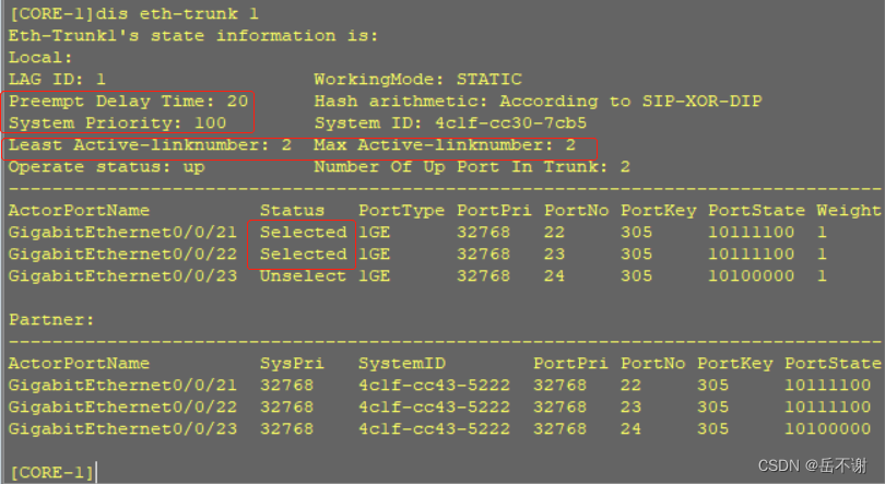
4.4 在核心层与汇聚层采用MSTP,实现流量负载分担。
一是使学生宿舍区、教学楼区、实训楼区和行政楼区走CORE-1,二是使图书馆区、体育馆区、食堂和室外及主要干道走CORE-2。CORE-1和CORE-2互为备份根。
(1)CORE-1
stp enable
stp mode mstp
stp region-configuration // 进入MSTP域试图MSTP配置模式
region-name XX-zyjsxy //配置MSTP域的域名为XX-zyjsxy
instance 1 vlan 20 500
instance 2 vlan 21 510
instance 3 vlan 22 200 520
instance 4 vlan 66 530
instance 5 vlan 50 540
instance 6 vlan 60 550
instance 7 vlan 70 560
instance 8 vlan 570
instance 9 vlan 210
active region-configuration //激活MSTP域的配置
quit
stp instance 1 root primary //配置CORE-1为实例1、2、3、4的主根桥
stp instance 2 root primary
stp instance 3 root primary
stp instance 4 root primary
stp instance 5 root secondary //配置CORE-1为实例5、6、7、8的备份根桥
stp instance 6 root secondary
stp instance 7 root secondary
stp instance 8 root secondary
stp instance 9 root primary
(2)CORE-2
stp enable
stp mode mstp
stp region-configuration
region-name XX-zyjsxy
instance 1 vlan 20 500
instance 2 vlan 21 510
instance 3 vlan 22 200 520
instance 4 vlan 66 530
instance 5 vlan 50 540
instance 6 vlan 60 550
instance 7 vlan 70 560
instance 8 vlan 570
instance 9 vlan 210
active region-configuration
quit
stp instance 1 root secondary //配置CORE-2为实例1、2、3、4、9的备份根桥
stp instance 2 root secondary
stp instance 3 root secondary
stp instance 4 root secondary
stp instance 5 root primary //配置CORE-2为实例5、6、7、8的主根桥
stp instance 6 root primary
stp instance 7 root primary
stp instance 8 root primary
stp instance 9 root secondary
(3)学生宿舍区汇聚层交换机配置MSTP
stp enable
stp mode mstp
stp region-configuration
region-name XX-zyjsxy
instance 1 vlan 20 500
instance 2 vlan 21 510
instance 3 vlan 22 200 520
instance 4 vlan 66 530
instance 5 vlan 50 540
instance 6 vlan 60 550
instance 7 vlan 70 560
instance 8 vlan 570
instance 9 vlan 210
active region-configuration
quit
(4)教学楼区汇聚层交换机配置MSTP
stp enable
stp mode mstp
stp region-configuration
region-name XX-zyjsxy
instance 1 vlan 20 500
instance 2 vlan 21 510
instance 3 vlan 22 200 520
instance 4 vlan 66 530
instance 5 vlan 50 540
instance 6 vlan 60 550
instance 7 vlan 70 560
instance 8 vlan 570
instance 9 vlan 210
active region-configuration
quit
(5)实训楼区汇聚层交换机配置MSTP
stp enable
stp mode mstp
stp region-configuration
region-name XX-zyjsxy
instance 1 vlan 20 500
instance 2 vlan 21 510
instance 3 vlan 22 200 520
instance 4 vlan 66 530
instance 5 vlan 50 540
instance 6 vlan 60 550
instance 7 vlan 70 560
instance 8 vlan 570
instance 9 vlan 210
active region-configuration
quit
(6)行政楼区汇聚层交换机配置MSTP
stp enable
stp mode mstp
stp region-configuration
region-name XX-zyjsxy
instance 1 vlan 20 500
instance 2 vlan 21 510
instance 3 vlan 22 200 520
instance 4 vlan 66 530
instance 5 vlan 50 540
instance 6 vlan 60 550
instance 7 vlan 70 560
instance 8 vlan 570
instance 9 vlan 210
active region-configuration
quit
(7)图书馆区汇聚层交换机配置MSTP
stp enable
stp mode mstp
stp region-configuration
region-name XX-zyjsxy
instance 1 vlan 20 500
instance 2 vlan 21 510
instance 3 vlan 22 200 520
instance 4 vlan 66 530
instance 5 vlan 50 540
instance 6 vlan 60 550
instance 7 vlan 70 560
instance 8 vlan 570
instance 9 vlan 210
active region-configuration
quit
(8)体育馆区汇聚层交换机配置MSTP
stp enable
stp mode mstp
stp region-configuration
region-name XX-zyjsxy
instance 1 vlan 20 500
instance 2 vlan 21 510
instance 3 vlan 22 200 520
instance 4 vlan 66 530
instance 5 vlan 50 540
instance 6 vlan 60 550
instance 7 vlan 70 560
instance 8 vlan 570
instance 9 vlan 210
active region-configuration
quit
(9)食堂区汇聚层交换机配置MSTP
stp enable
stp mode mstp
stp region-configuration
region-name XX-zyjsxy
instance 1 vlan 20 500
instance 2 vlan 21 510
instance 3 vlan 22 200 520
instance 4 vlan 66 530
instance 5 vlan 50 540
instance 6 vlan 60 550
instance 7 vlan 70 560
instance 8 vlan 570
instance 9 vlan 210
active region-configuration
quit
(10)室外及主要干道区汇聚层交换机配置MSTP
stp enable
stp mode mstp
stp region-configuration
region-name XX-zyjsxy
instance 1 vlan 20 500
instance 2 vlan 21 510
instance 3 vlan 22 200 520
instance 4 vlan 66 530
instance 5 vlan 50 540
instance 6 vlan 60 550
instance 7 vlan 70 560
instance 8 vlan 570
instance 9 vlan 210
active region-configuration
quit
(11)AC配置MSTP防止环以及起到链路备份
stp enable
stp mode mstp
stp region-configuration
region-name XX-zyjsxy
instance 1 vlan 20 500
instance 2 vlan 21 510
instance 3 vlan 22 200 520
instance 4 vlan 66 530
instance 5 vlan 50 540
instance 6 vlan 60 550
instance 7 vlan 70 560
instance 8 vlan 570
instance 9 vlan 210
active region-configuration
quit
验证结果:


4.5 配置DHCP服务,使用户的设备动态获取IP地址,采用双DHCP配置,进行备份
在DHCP server1和DHCP server2上做地址池,创建有线网络的地址池以及无线网络的管理AP的和无线设备的地址池。
(1)DHCP server1和DHCP server2配置相同
dhcp enable
ip pool vlan20
gateway-list 10.0.10.1
network 10.0.10.0 mask 20
excluded-ip-address 10.0.10.2 10.0.10.3
lease day 2
dns-list 8.8.8.8 114.114.114.114
ip pool vlan21
gateway-list 172.17.6.1
network 172.17.6.0 mask 23
excluded-ip-address 172.17.6.2 172.17.6.3
lease day 2
dns-list 8.8.8.8 114.114.114.114
ip pool vlan22
gateway-list 172.17.10.1
network 172.17.10.0 mask 23
excluded-ip-address 172.17.10.2 172.17.10.3
lease day 2
dns-list 8.8.8.8 114.114.114.114
ip pool vlan200
gateway-list 192.168.10.1
network 192.168.10.0 mask 24
excluded-ip-address 192.168.10.2 192.168.10.3
lease day 2
dns-list 8.8.8.8 114.114.114.114
ip pool vlan66
gateway-list 172.17.66.1
network 172.17.66.0 mask 23
excluded-ip-address 172.17.66.2 172.17.66.3
lease day 2
dns-list 8.8.8.8 114.114.114.114
ip pool vlan50
gateway-list 172.17.50.1
network 172.17.50.0 mask 23
excluded-ip-address 172.17.50.2 172.17.50.3
lease day 2
dns-list 8.8.8.8 114.114.114.114
ip pool vlan60
gateway-list 172.17.60.1
network 172.17.60.0 mask 23
excluded-ip-address 172.17.60.2 172.17.60.3
lease day 2
dns-list 8.8.8.8 114.114.114.114
ip pool vlan70
gateway-list 172.17.70.1
network 172.17.70.0 mask 23
excluded-ip-address 172.17.70.2 172.17.70.3
lease day 2
dns-list 8.8.8.8 114.114.114.114
ip pool vlan500
gateway-list 192.10.10.1
network 192.10.10.0 mask 24
excluded-ip-address 192.10.10.2 192.10.10.3
lease day 2
dns-list 8.8.8.8 114.114.114.114
ip pool vlan510
gateway-list 192.10.20.1
network 192.10.20.0 mask 24
excluded-ip-address 192.10.20.2 192.10.20.3
lease day 2
dns-list 8.8.8.8 114.114.114.114
ip pool vlan520
gateway-list 192.10.30.1
network 192.10.30.0 mask 24
excluded-ip-address 192.10.30.2 192.10.30.3
lease day 2
dns-list 8.8.8.8 114.114.114.114
ip pool vlan530
gateway-list 192.10.40.1
network 192.10.40.0 mask 24
excluded-ip-address 192.10.40.2 192.10.40.3
lease day 2
dns-list 8.8.8.8 114.114.114.114
ip pool vlan540
gateway-list 192.10.50.1
network 192.10.50.0 mask 24
excluded-ip-address 192.10.50.2 192.10.50.3
lease day 2
dns-list 8.8.8.8 114.114.114.114
ip pool vlan550
gateway-list 192.10.60.1
network 192.10.60.0 mask 24
excluded-ip-address 192.10.60.2 192.10.60.3
lease day 2
dns-list 8.8.8.8 114.114.114.114
ip pool vlan560
gateway-list 192.10.70.1
network 192.10.70.0 mask 24
excluded-ip-address 192.10.70.2 192.10.70.3
lease day 2
dns-list 8.8.8.8 114.114.114.114
ip pool vlan570
gateway-list 192.10.80.1
network 192.10.80.0 mask 24
excluded-ip-address 192.10.80.2 192.10.80.3
lease day 2
dns-list 8.8.8.8 114.114.114.114
ip pool vlan202
gateway-list 10.202.1.1
network 10.202.1.0 mask 17
excluded-ip-address 10.202.1.2 10.202.1.3
lease day 2
dns-list 8.8.8.8 114.114.114.114
ip pool vlan203
gateway-list 10.203.1.1
network 10.203.1.0 mask 19
excluded-ip-address 10.203.1.2 10.203.1.3
lease day 2
dns-list 8.8.8.8 114.114.114.114
ip pool vlan204
gateway-list 10.204.1.1
network 10.204.1.0 mask 19
excluded-ip-address 10.204.1.2 10.204.1.3
lease day 2
dns-list 8.8.8.8 114.114.114.114
(2)DHCP server1的端口IP地址配置及DHCP服务的下发配置
int g0/0/0
ip address 172.10.3.1 24
quit
int g0/0/1
ip address 172.10.1.2 24
dhcp select global
quit
(3)DHCP server2的端口IP地址配置及DHCP服务的下发配置
int g0/0/0
ip address 172.10.4.1 24
quit
int g0/0/1
ip address 172.10.2.2 24
dhcp select global
quit
(4)在DHCP server1和DHCP server2分别配置默认路由
[DHCP-server1]ip route-static 0.0.0.0 0 172.10.1.1
[DHCP-server2]ip route-static 0.0.0.0 0 172.10.2.1
(5)在CORE-1和CORE-2上配置DHCP服务中继
CORE1
interface Vlanif2
ip add 172.10.1.1 24
dhcp enable
dhcp server group XX-zyjsxy //创建DHCP server组,组名为XX-zyjsxy
dhcp-server 172.10.1.2 //指定DHCP server接口地址
quit
interface Vlanif20
ip address 10.0.10.2 20
dhcp select relay //配置中继
dhcp relay server-select XX-zyjsxy
quit
interface Vlanif500
ip address 192.10.10.2 24
dhcp select relay
dhcp relay server-select XX-zyjsxy
quit
interface Vlanif21
ip address 172.17.6.2 23
dhcp select relay
dhcp relay server-select XX-zyjsxy
quit
interface Vlanif510
ip address 192.10.20.2 24
dhcp select relay
dhcp relay server-select XX-zyjsxy
quit
interface Vlanif22
ip address 172.17.10.2 23
dhcp select relay
dhcp relay server-select XX-zyjsxy
quit
interface Vlanif200
ip address 192.168.10.2 24
dhcp select relay
dhcp relay server-select XX-zyjsxy
quit
interface Vlanif520
ip address 192.10.30.2 24
dhcp select relay
dhcp relay server-select XX-zyjsxy
quit
interface Vlanif66
ip address 172.17.66.2 23
dhcp select relay
dhcp relay server-select XX-zyjsxy
quit
interface Vlanif530
ip address 192.10.40.2 24
dhcp select relay
dhcp relay server-select XX-zyjsxy
quit
interface Vlanif50
ip address 172.17.50.2 23
dhcp select relay
dhcp relay server-select XX-zyjsxy
quit
interface Vlanif540
ip address 192.10.50.2 24
dhcp select relay
dhcp relay server-select XX-zyjsxy
quit
interface Vlanif60
ip address 172.17.60.2 23
dhcp select relay
dhcp relay server-select XX-zyjsxy
quit
interface Vlanif550
ip address 192.10.60.2 24
dhcp select relay
dhcp relay server-select XX-zyjsxy
quit
interface Vlanif70
ip address 172.17.70.2 23
dhcp select relay
dhcp relay server-select XX-zyjsxy
quit
interface Vlanif560
ip address 192.10.70.2 24
dhcp select relay
dhcp relay server-select XX-zyjsxy
quit
interface Vlanif570
ip address 192.10.80.2 24
dhcp select relay
dhcp relay server-select XX-zyjsxy
quit
interface Vlanif202
ip address 10.202.1.2 17
dhcp select relay
dhcp relay server-select XX-zyjsxy
quit
interface Vlanif203
ip address 10.203.1.2 19
dhcp select relay
dhcp relay server-select XX-zyjsxy
quit
interface Vlanif204
ip address 10.204.1.2 19
dhcp select relay
dhcp relay server-select XX-zyjsxy
quit
CORE2
interface Vlanif2
ip add 172.10.2.1 24
dhcp enable
dhcp server group XX-zyjsxy
dhcp-server 172.10.2.2
quit
interface Vlanif20
ip address 10.0.10.3 20
dhcp select relay
dhcp relay server-select XX-zyjsxy
quit
interface Vlanif500
ip address 192.10.10.3 24
dhcp select relay
dhcp relay server-select XX-zyjsxy
quit
interface Vlanif21
ip address 172.17.6.3 23
dhcp select relay
dhcp relay server-select XX-zyjsxy
quit
interface Vlanif510
ip address 192.10.20.3 24
dhcp select relay
dhcp relay server-select XX-zyjsxy
quit
interface Vlanif22
ip address 172.17.10.3 23
dhcp select relay
dhcp relay server-select XX-zyjsxy
quit
interface Vlanif200
ip address 192.168.10.3 24
dhcp select relay
dhcp relay server-select XX-zyjsxy
quit
interface Vlanif520
ip address 192.10.30.3 24
dhcp select relay
dhcp relay server-select XX-zyjsxy
quit
interface Vlanif66
ip address 172.17.66.3 23
dhcp select relay
dhcp relay server-select XX-zyjsxy
quit
interface Vlanif530
ip address 192.10.40.3 24
dhcp select relay
dhcp relay server-select XX-zyjsxy
quit
interface Vlanif50
ip address 172.17.50.3 23
dhcp select relay
dhcp relay server-select XX-zyjsxy
quit
interface Vlanif540
ip address 192.10.50.3 24
dhcp select relay
dhcp relay server-select XX-zyjsxy
quit
interface Vlanif60
ip address 172.17.60.3 23
dhcp select relay
dhcp relay server-select XX-zyjsxy
quit
interface Vlanif550
ip address 192.10.60.3 24
dhcp select relay
dhcp relay server-select XX-zyjsxy
quit
interface Vlanif70
ip address 172.17.70.3 23
dhcp select relay
dhcp relay server-select XX-zyjsxy
quit
interface Vlanif560
ip address 192.10.70.3 24
dhcp select relay
dhcp relay server-select XX-zyjsxy
quit
interface Vlanif570
ip address 192.10.80.3 24
dhcp select relay
dhcp relay server-select XX-zyjsxy
quit
interface Vlanif202
ip address 10.202.1.3 17
dhcp select relay
dhcp relay server-select XX-zyjsxy
quit
interface Vlanif203
ip address 10.203.1.3 19
dhcp select relay
dhcp relay server-select XX-zyjsxy
quit
interface Vlanif204
ip address 10.204.1.3 19
dhcp select relay
dhcp relay server-select XX-zyjsxy
quit
验证结果:
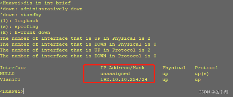
(1)AP自动获取IP地址
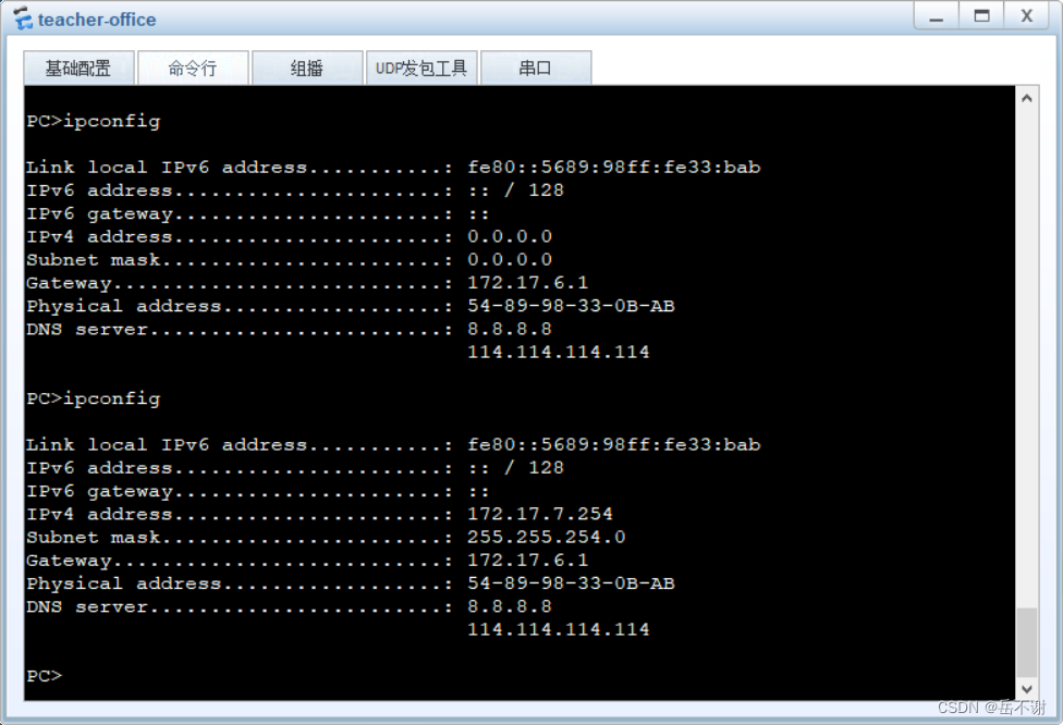
(2)PC自动获取IP地址
4.6 在CORE-1和CORE-2配置VRRP,实现冗余备份
(1)CORE-1
interface Vlanif20
vrrp vrid 1 virtual-ip 10.0.10.1
vrrp vrid 1 priority 120 //配置优先级,选为主设备
vrrp vrid 1 track interface GigabitEthernet 0/0/1 reduced 50 //配置VRRP接口监测联动,监测上联接口
vrrp vrid 1 preempt-mode timer delay 20 //配置抢占延时避免频繁抢占导致的出口网关动荡
quit
interface Vlanif500
vrrp vrid 2 virtual-ip 192.10.10.1
vrrp vrid 2 priority 120
vrrp vrid 2 track interface GigabitEthernet 0/0/1 reduced 50
vrrp vrid 2 preempt-mode timer delay 20
quit
interface Vlanif21
vrrp vrid 3 virtual-ip 172.17.6.1
vrrp vrid 3 priority 120
vrrp vrid 3 track interface GigabitEthernet 0/0/1 reduced 50
vrrp vrid 3 preempt-mode timer delay 20
quit
interface Vlanif510
vrrp vrid 4 virtual-ip 192.10.20.1
vrrp vrid 4 priority 120
vrrp vrid 4 track interface GigabitEthernet 0/0/1 reduced 50
vrrp vrid 4 preempt-mode timer delay 20
quit
interface Vlanif22
vrrp vrid 5 virtual-ip 172.17.10.1
vrrp vrid 5 priority 120
vrrp vrid 5 track interface GigabitEthernet 0/0/1 reduced 50
vrrp vrid 5 preempt-mode timer delay 20
quit
interface Vlanif200
vrrp vrid 6 virtual-ip 192.168.10.1
vrrp vrid 6 priority 120
vrrp vrid 6 track interface GigabitEthernet 0/0/1 reduced 50
vrrp vrid 6 preempt-mode timer delay 20
quit
interface Vlanif520
vrrp vrid 7 virtual-ip 192.10.30.1
vrrp vrid 7 priority 120
vrrp vrid 7 track interface GigabitEthernet 0/0/1 reduced 50
vrrp vrid 7 preempt-mode timer delay 20
quit
interface Vlanif66
vrrp vrid 8 virtual-ip 172.17.66.1
vrrp vrid 8 priority 120
vrrp vrid 8 track interface GigabitEthernet 0/0/1 reduced 50
vrrp vrid 8 preempt-mode timer delay 20
quit
interface Vlanif530
vrrp vrid 9 virtual-ip 192.10.40.1
vrrp vrid 9 priority 120
vrrp vrid 9 track interface GigabitEthernet 0/0/1 reduced 50
vrrp vrid 9 preempt-mode timer delay 20
quit
interface Vlanif50
vrrp vrid 10 virtual-ip 172.17.50.1
vrrp vrid 10 preempt-mode timer delay 20
quit
interface Vlanif540
vrrp vrid 11 virtual-ip 192.10.50.1
vrrp vrid 11 preempt-mode timer delay 20
quit
interface Vlanif60
vrrp vrid 12 virtual-ip 172.17.60.1
vrrp vrid 12 preempt-mode timer delay 20
quit
interface Vlanif550
vrrp vrid 13 virtual-ip 192.10.60.1
vrrp vrid 13 preempt-mode timer delay 20
quit
interface Vlanif70
vrrp vrid 14 virtual-ip 172.17.70.1
vrrp vrid 14 preempt-mode timer delay 20
quit
interface Vlanif560
vrrp vrid 15 virtual-ip 192.10.70.1
vrrp vrid 15 preempt-mode timer delay 20
quit
interface Vlanif570
vrrp vrid 16 virtual-ip 192.10.80.1
vrrp vrid 16 preempt-mode timer delay 20
quit
interface Vlanif202
vrrp vrid 202 virtual-ip 10.202.1.1
vrrp vrid 202 priority 120
vrrp vrid 202 track interface GigabitEthernet 0/0/1 reduced 50
vrrp vrid 202 preempt-mode timer delay 20
quit
interface Vlanif203
vrrp vrid 203 virtual-ip 10.203.1.1
vrrp vrid 203 priority 120
vrrp vrid 203 track interface GigabitEthernet 0/0/1 reduced 50
vrrp vrid 203 preempt-mode timer delay 20
quit
interface Vlanif204
vrrp vrid 204 virtual-ip 10.204.1.1
vrrp vrid 204 priority 120
vrrp vrid 204 track interface GigabitEthernet 0/0/1 reduced 50
vrrp vrid 204 preempt-mode timer delay 20
quit
(2)CORE-2
interface Vlanif20
vrrp vrid 1 virtual-ip 10.0.10.1
vrrp vrid 1 preempt-mode timer delay 20
quit
interface Vlanif500
vrrp vrid 2 virtual-ip 192.10.10.1
vrrp vrid 2 preempt-mode timer delay 20
quit
interface Vlanif21
vrrp vrid 3 virtual-ip 172.17.6.1
vrrp vrid 3 preempt-mode timer delay 20
quit
interface Vlanif510
vrrp vrid 4 virtual-ip 192.10.20.1
vrrp vrid 4 preempt-mode timer delay 20
quit
interface Vlanif22
vrrp vrid 5 virtual-ip 172.17.10.1
vrrp vrid 5 preempt-mode timer delay 20
quit
interface Vlanif200
vrrp vrid 6 virtual-ip 192.168.10.1
vrrp vrid 6 preempt-mode timer delay 20
quit
interface Vlanif520
vrrp vrid 7 virtual-ip 192.10.30.1
vrrp vrid 7 preempt-mode timer delay 20
quit
interface Vlanif66
vrrp vrid 8 virtual-ip 172.17.66.1
vrrp vrid 8 preempt-mode timer delay 20
quit
interface Vlanif530
vrrp vrid 9 virtual-ip 192.10.40.1
vrrp vrid 9 preempt-mode timer delay 20
quit
interface Vlanif50
vrrp vrid 10 virtual-ip 172.17.50.1
vrrp vrid 10 priority 120
vrrp vrid 10 track interface GigabitEthernet 0/0/1 reduced 50
vrrp vrid 10 preempt-mode timer delay 20
quit
interface Vlanif540
vrrp vrid 11 virtual-ip 192.10.50.1
vrrp vrid 11 priority 120
vrrp vrid 11 track interface GigabitEthernet 0/0/1 reduced 50
vrrp vrid 11 preempt-mode timer delay 20
quit
interface Vlanif60
vrrp vrid 12 virtual-ip 172.17.60.1
vrrp vrid 12 priority 120
vrrp vrid 12 track interface GigabitEthernet 0/0/1 reduced 50
vrrp vrid 12 preempt-mode timer delay 20
quit
interface Vlanif550
vrrp vrid 13 virtual-ip 192.10.60.1
vrrp vrid 13 priority 120
vrrp vrid 13 track interface GigabitEthernet 0/0/1 reduced 50
vrrp vrid 13 preempt-mode timer delay 20
quit
interface Vlanif70
vrrp vrid 14 virtual-ip 172.17.70.1
vrrp vrid 14 priority 120
vrrp vrid 14 track interface GigabitEthernet 0/0/1 reduced 50
vrrp vrid 14 preempt-mode timer delay 20
quit
interface Vlanif560
vrrp vrid 15 virtual-ip 192.10.70.1
vrrp vrid 15 priority 120
vrrp vrid 15 track interface GigabitEthernet 0/0/1 reduced 50
vrrp vrid 15 preempt-mode timer delay 20
quit
interface Vlanif570
vrrp vrid 16 virtual-ip 192.10.80.1
vrrp vrid 16 priority 120
vrrp vrid 16 track interface GigabitEthernet 0/0/1 reduced 50
vrrp vrid 16 preempt-mode timer delay 20
quit
interface Vlanif202
vrrp vrid 202 virtual-ip 10.202.1.1
vrrp vrid 202 preempt-mode timer delay 20
quit
interface Vlanif203
vrrp vrid 203 virtual-ip 10.203.1.1
vrrp vrid 203 preempt-mode timer delay 20
quit
interface Vlanif204
vrrp vrid 204 virtual-ip 10.204.1.1
vrrp vrid 204 preempt-mode timer delay 20
quit
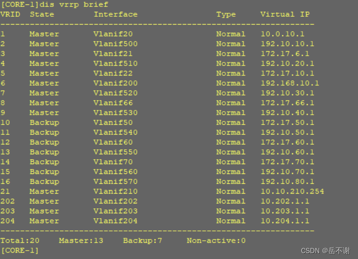
验证结果:
五、无线的配置
通过结合有线的基础,拓展校园的无线网络,对校园网进行覆盖,使全校的师生能够随时随地访问校园的学习资源。
5.1 配置AP在AC注册上线
(1)配置AC服务器
[AC]vlan 210
int vlan 210
ip add 10.10.210.1 24
quit
interface GigabitEthernet0/0/1
port link-type access
port default vlan 210
quit
interface GigabitEthernet0/0/2
port link-type access
port default vlan 210
quit
port default vlan 210
ip route-static 0.0.0.0 0 10.10.210.254
(2)配置核心交换机,添加vlan210
CORE-1配置:
int vlan 210
ip add 10.10.210.2 24
vrrp vrid 21 virtual-ip 10.10.210.254
vrrp vrid 21 priority 120
vrrp vrid 21 preempt-mode timer delay 20
quit
interface GigabitEthernet0/0/19
port link-type access
port default vlan 210
quit
CORE-2配置:
int vlan 210
ip add 10.10.210.3 24
vrrp vrid 21 virtual-ip 10.10.210.254
vrrp vrid 21 preempt-mode timer delay 20
quit
interface GigabitEthernet0/0/19
port link-type access
port default vlan 210
quit
(3)配置DHCP服务器,为AP管理地址池配置AC服务器的地址
DHCP server1和DHCP server2配置相同
ip pool vlan500
option 43 sub-option 3 ascii 10.10.210.1
quit
ip pool vlan510
option 43 sub-option 3 ascii 10.10.210.1
quit
ip pool vlan520
option 43 sub-option 3 ascii 10.10.210.1
quit
ip pool vlan530
option 43 sub-option 3 ascii 10.10.210.1
quit
ip pool vlan540
option 43 sub-option 3 ascii 10.10.210.1
quit
ip pool vlan550
option 43 sub-option 3 ascii 10.10.210.1
quit
ip pool vlan560
option 43 sub-option 3 ascii 10.10.210.1
quit
ip pool vlan570
option 43 sub-option 3 ascii 10.10.210.1
quit
(4)重启AP,让AP获取AC服务器地址
(5)配置AC服务器,允许AP注册
1)指定CAPWAP协议的信令源地址
capwap source interface Vlanif 210
2)指定AC的验证方式为MAC地址验证
[AC]wlan
ap auth-mode mac-auth
3)创建ap-group(AP组),便于日后对AP的批量管理
ap-group name xueshengsushe //学生宿舍楼区域的AP,以学生宿舍楼区命名AP组
quit
ap-group name jiaoxuelou //教学楼区域
quit
ap-group name shixunlou //实训楼区域
quit
ap-group name xingzhenglou //行政楼区域
quit
ap-group name tushuguan //图书馆区域
quit
ap-group name tiyuguan //体育馆区域
quit
ap-group name shitang //食堂区域
quit
ap-group name outdoor //户外及主要干道区域
quit
4)创建“域配置文件”,指定AP无线频率范围
[AC-wlan-view]regulatory-domain-profile name China
[AC-wlan-regulate-domain-China]country-code CN
[AC-wlan-regulate-domain-China]quit
5)将配置好的“域配置文件”关联到每一个ap-group
[AC-wlan-view]ap-group name xueshengsushe
[AC-wlan-ap-group-xueshengsushe]regulatory-domain-profile China
Warning: Modifying the country code will clear channel, power and antenna gain c
onfigurations of the radio and reset the AP. Continue?[Y/N]:y
[AC-wlan-ap-group-xueshengsushe]quit
ap-group name jiaoxuelou
regulatory-domain-profile China
y
quit
ap-group name shixunlou
regulatory-domain-profile China
y
quit
ap-group name xingzhenglou
regulatory-domain-profile China
y
quit
ap-group name tushuguan
regulatory-domain-profile China
y
quit
ap-group name tiyuguan
regulatory-domain-profile China
y
quit
ap-group name shitang
regulatory-domain-profile China
y
quit
ap-group name outdoor
regulatory-domain-profile China
y
quit
6)在AC上手动添加ap(基于MAC地址进行注册)
启动AP可通过查看AP端口获取MAC地址,例如display interface GigabitEthernet0/0/0
[AC-wlan-view]ap-id 1 ap-mac 00e0-fc3a-5ba0
[AC-wlan-ap-1]ap-name xueshengsushe-1 //为AP设置名字,便于区分AP点位
[AC-wlan-ap-1]ap-group xueshengsushe //将AP加入指定的AP组中
Warning: This operation may cause AP reset. If the country code changes, it will clear channel, power and antenna gain configurations of the radio, Whether to continue? [Y/N]:y
Info: This operation may take a few seconds. Please wait for a moment.. done.
[AC-wlan-ap-1]quit
ap-id 2 ap-mac 00e0-fc3e-24f0
ap-name jiaoxuelou-1
ap-group jiaoxuelou
y
quit
ap-id 3 ap-mac 00e0-fcf4-2960
ap-name shixunlou-1
ap-group shixunlou
y
quit
ap-id 4 ap-mac 00e0-fc6f-0b40
ap-name xingzhenglou-1
ap-group xingzhenglou
y
quit
ap-id 5 ap-mac 00e0-fc9b-53e0
ap-name tushuguan-1
ap-group tushuguan
y
quit
ap-id 6 ap-mac 00e0-fcb1-7330
ap-name tiyuguan-1
ap-group tiyuguan
y
quit
ap-id 7 ap-mac 00e0-fc4d-5880
ap-name shitang-1
ap-group shitang
y
quit
ap-id 8 ap-mac 00e0-fc0a-5eb0
ap-name outdoor-1
ap-group outdoor
y
quit
(6)在AP上验证是否注册成功

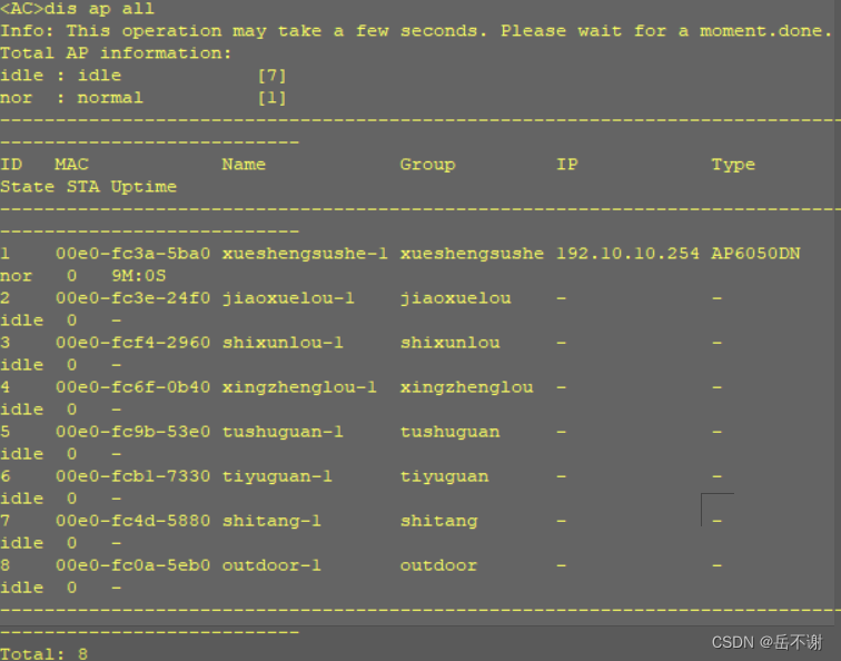
(7)在AC上验证是否注册成功
5.2 通过AC为AP设备分配无线参数
(1)创建业务vlan地址池
[AC]vlan pool sta-student
[AC-vlan-pool-sta-student]vlan 202
[AC-vlan-pool-sta-student]quit
[AC] vlan pool sta-teacher
[AC-vlan-pool-sta-teacher]vlan 203
[AC-vlan-pool-sta-teacher]quit
[AC]vlan pool sta-public
[AC-vlan-pool-sta-public]vlan 204
[AC-vlan-pool-sta-public]quit
[AC]vlan pool sta-guest
[AC-vlan-pool-sta-guest]vlan 204
[AC-vlan-pool-sta-guest]quit
(2)设置加密配置文件,为AP分配无线密码
[AC]wlan
[AC-wlan-view]security-profile name student
[AC-wlan-sec-prof-student]security wpa2 psk pass-phrase student123 aes
[AC-wlan-sec-prof-student]quit
security-profile name teacher
security wpa2 psk pass-phrase teacher123 aes
quit
security-profile name public
security wpa2 psk pass-phrase public123 aes
quit
security-profile name guest
security wpa2 psk pass-phrase guest123 aes
quit
(3)设置ssid名称,为AP分配无线信号的名称
[AC-wlan-view]ssid-profile name student
[AC-wlan-ssid-prof-student]ssid student
[AC-wlan-ssid-prof-student]quit
ssid-profile name teacher
ssid teacher
quit
ssid-profile name public
ssid public
quit
ssid-profile name guest
ssid guest
quit
(4)创建无线客户端访问模板,关联以上三个参数
[AC-wlan-view]vap-profile name student
[AC-wlan-vap-prof-student]service-vlan vlan-pool sta-student
[AC-wlan-vap-prof-student]security-profile student
[AC-wlan-vap-prof-student]ssid-profile student
[AC-wlan-vap-prof-student]quit
vap-profile name teacher
service-vlan vlan-pool sta-teacher
security-profile teacher
ssid-profile teacher
quit
vap-profile name public
service-vlan vlan-pool sta-public
security-profile public
ssid-profile public
quit
vap-profile name guest
service-vlan vlan-pool sta-guest
security-profile guest
ssid-profile guest
quit
(5)开启AP无线信号
[AC-wlan-view]ap-group name xueshengsushe
[AC-wlan-ap-group-xueshengsushe]vap-profile student wlan 1 radio all
[AC-wlan-ap-group-xueshengsushe] vap-profile teacher wlan 2 radio all
quit
ap-group name jiaoxuelou
vap-profile student wlan 1 radio all
vap-profile teacher wlan 2 radio all
vap-profile public wlan 3 radio all
vap-profile guest wlan 4 radio all
quit
ap-group name shixunlou
vap-profile student wlan 1 radio all
vap-profile teacher wlan 2 radio all
vap-profile public wlan 3 radio all
vap-profile guest wlan 4 radio all
quit
ap-group name xingzhenglou
vap-profile student wlan 1 radio all
vap-profile teacher wlan 2 radio all
vap-profile public wlan 3 radio all
vap-profile guest wlan 4 radio all
quit
ap-group name tushuguan
vap-profile student wlan 1 radio all
vap-profile teacher wlan 2 radio all
vap-profile public wlan 3 radio all
vap-profile guest wlan 4 radio all
quit
ap-group name tiyuguan
vap-profile student wlan 1 radio all
vap-profile teacher wlan 2 radio all
vap-profile public wlan 3 radio all
vap-profile guest wlan 4 radio all
quit
ap-group name shitang
vap-profile student wlan 1 radio all
vap-profile teacher wlan 2 radio all
vap-profile public wlan 3 radio all
vap-profile guest wlan 4 radio all
quit
ap-group name outdoor
vap-profile student wlan 1 radio all
vap-profile teacher wlan 2 radio all
vap-profile public wlan 3 radio all
vap-profile guest wlan 4 radio all
六、防火墙的配置
6.1在防火墙接口上对各区域进行划分
(1)进入信任区域(Trust),添加连接内网的端口(注意防火墙是将接口下的设备加入到区域内,并不是接口加入到区域,防火墙上所有接口都属于local区域)
[USG6000V1]firewall zone trust
[USG6000V1-zone-trust] add interface GigabitEthernet 1/0/1
[USG6000V1-zone-trust]add interface GigabitEthernet 1/0/2
[USG6000V1-zone-trust]quit
(2)进入DMZ区域,添加连接服务器集群的端口
firewall zone dmz
add interface GigabitEthernet 1/0/0
quit
(3)进入不信任区域(UNtrust),添加连接网络服务提供商的端口
firewall zone untrust
add interface GigabitEthernet 1/0/5
add interface GigabitEthernet 1/0/4
quit
(4)进入教育网区域(edu_zone),添加连接到教育网的端口
firewall zone name edu.com
set priority 25
add interface GigabitEthernet 1/0/3
quit
6.2配置端口的IP地址以及路由
(1)配置FW端口的IP地址
interface GigabitEthernet1/0/0
ip address 172.17.5.1 24
quit
interface GigabitEthernet1/0/1
ip address 172.10.3.2 24
quit
interface GigabitEthernet1/0/2
ip address 172.10.4.2 24
quit
interface GigabitEthernet1/0/3
ip address 101.10.10.1 24
quit
interface GigabitEthernet1/0/4
ip address 121.10.10.1 24
quit
interface GigabitEthernet1/0/5
ip address 112.10.10.1 24
quit
(2)在edu.com上配置edu.com端口IP地址
[edu.com]interface GigabitEthernet0/0/0
ip address 101.10.10.2 24
quit
(3)在ISP-1上配置ISP-1端口IP地址
[ISP-1]interface GigabitEthernet0/0/0
ip address 112.10.10.2 24
quit
interface GigabitEthernet0/0/1
ip address 113.10.10.1 24
quit
(4)在ISP-2上配置ISP-2端口IP地址
[ISP-2]interface GigabitEthernet0/0/0
ip address 121.10.10.2 24
quit
(5)在FW配置路由
1)配置通往外部的缺省路由
ip route-static 0.0.0.0 0 101.10.10.2
ip route-static 0.0.0.0 0 112.10.10.2
ip route-static 0.0.0.0 0 121.10.10.2
2)配置动态路由OSPF
[USG6000V1]ospf 1 router-id 5.5.5.5
[USG6000V1-ospf-1]area 0
[USG6000V1-ospf-1-area-0.0.0.0]network 172.17.5.0 0.0.0.255
[USG6000V1-ospf-1-area-0.0.0.0]network 172.17.6.0 0.0.0.255
[USG6000V1-ospf-1-area-0.0.0.0]network 172.10.3.0 0.0.0.255
[USG6000V1-ospf-1-area-0.0.0.0]network 172.10.4.0 0.0.0.255
[USG6000V1-ospf-1-area-0.0.0.0]network 101.10.10.0 0.0.0.255
[USG6000V1-ospf-1-area-0.0.0.0]network 112.10.10.0 0.0.0.255
[USG6000V1-ospf-1-area-0.0.0.0]network 121.10.10.0 0.0.0.255
3)在DHCP server1配置缺省路由通往FW
ip route-static 0.0.0.0 0 172.10.3.2
4)在DHCP server2配置缺省路由通往FW
ip route-static 0.0.0.0 0 172.10.4.2
5)在DHCP server1配置动态路由
ospf 1 router-id 3.3.3.3
area 0
network 172.10.3.0 0.0.0.255
network 172.10.1.0 0.0.0.255
6)在DHCP server2配置动态路由
ospf 1 router-id 4.4.4.4
area 0
network 172.10.4.0 0.0.0.255
network 172.10.2.0 0.0.0.255
7)在CORE-1配置动态路由
ospf 1 router-id 1.1.1.1
area 0
network 172.10.1.0 0.0.0.255
quit
8)在CORE-2配置动态路由
ospf 1 router-id 2.2.2.2
area 0
network 172.10.2.0 0.0.0.255
quit
9)在FW配置通回路路由
ip route-static 10.0.10.0 20 172.10.3.1
ip route-static 172.17.6.0 23 172.10.3.1
ip route-static 172.17.10.0 23 172.10.3.1
ip route-static 192.168.10.0 24 172.10.3.1
ip route-static 172.17.66.0 23 172.10.3.1
ip route-static 172.17.50.0 23 172.10.3.1
ip route-static 172.17.60.0 23 172.10.3.1
ip route-static 172.17.70.0 23 172.10.3.1
ip route-static 10.202.1.0 17 172.10.3.1
ip route-static 10.203.1.0 19 172.10.3.1
ip route-static 10.204.1.0 19 172.10.3.1
ip route-static 10.0.10.0 20 172.10.4.1
ip route-static 172.17.6.0 23 172.10.4.1
ip route-static 172.17.10.0 23 172.10.4.1
ip route-static 192.168.10.0 24 172.10.4.1
ip route-static 172.17.66.0 23 172.10.4.1
ip route-static 172.17.50.0 23 172.10.4.1
ip route-static 172.17.60.0 23 172.10.4.1
ip route-static 172.17.70.0 23 172.10.4.1
ip route-static 10.202.1.0 17 172.10.4.1
ip route-static 10.203.1.0 19 172.10.4.1
ip route-static 10.204.1.0 19 172.10.4.1
6.3配置安全策略
首先内网访问DMZ区域服务器,但是服务器不可以主动访问内网(trust)区域。
对于不同角色配置不同的安全策略,保护校园网的安全。
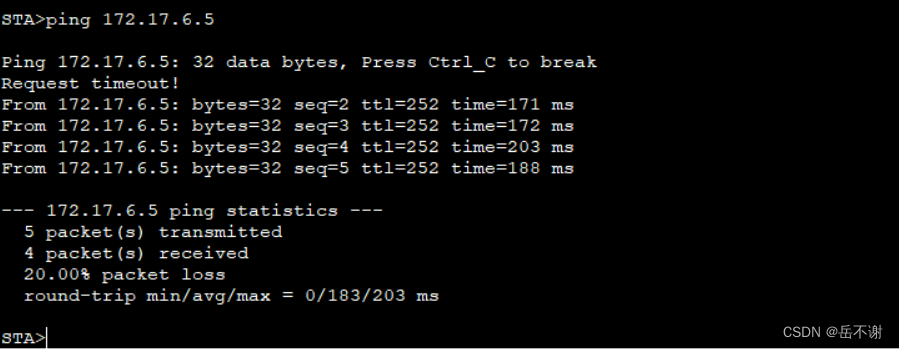
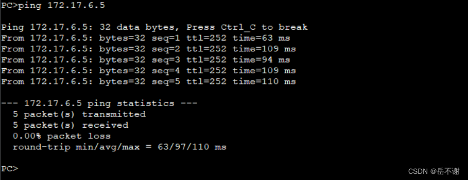
(1)内网访问校园WEB资源服务器和图书馆资源服务器
[USG6000V1]security-policy
rule name trust_to_dmz-1
source-zone trust
destination-zone dmz_1
action permit
验证测试:
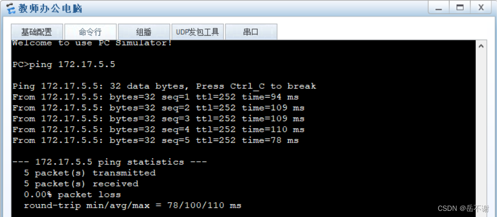
(2)校园师生访问教务系统服务器,教师访问FTP服务器
rule name trust_to_dmz
source-zone trust
destination-zone dmz
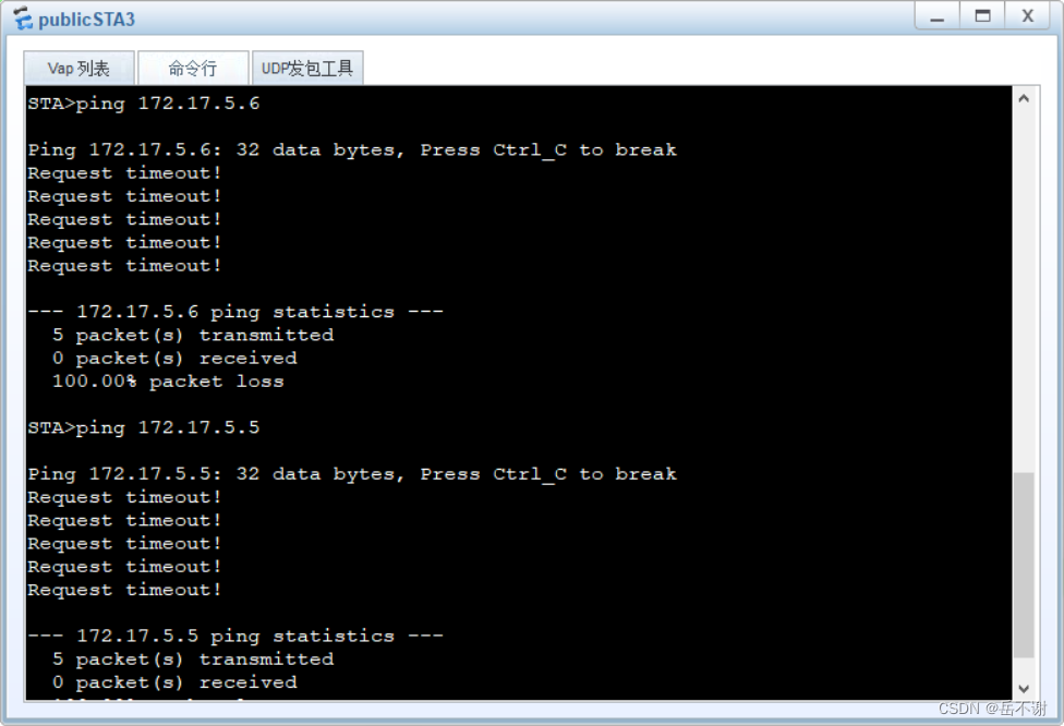
source-address-exclude 10.204.0.0 mask 255.255.224.0 //除了公用Wi-Fi或guest不能访问
action permit
公用WiFi无法访问教务系统验证测试
6.4配置NAT
首先进入安全策略视图下,创建安全策略规则名,接着配置放行的源区域和目的区域,规则动作允许放行;然后创建nat策略,配置规则名称,源区域和目的区域,最后内网与外网通过easy ip进行转换,同理,内网访问教育网配置也是类似。
(1)内网访问外网防火墙安全策略配置与NAT策略配置
[USG6000V1]security-policy
rule name trust_to_untrust
source-zone trust
destination-zone untrust
action permit
quit
[USG6000V1]nat-policy
rule name trust_to_untrust
source-zone trust
destination-zone untrust
action source-nat easy-ip
quit
验证测试:
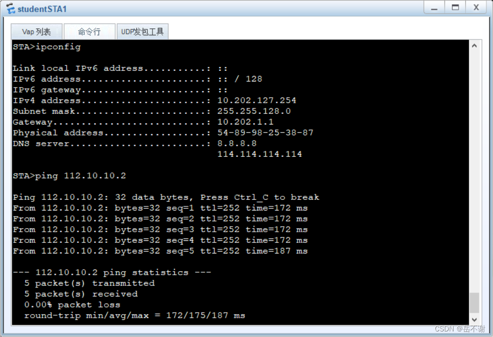
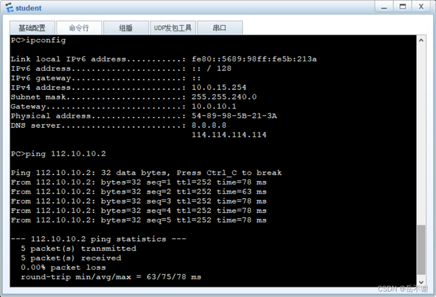
(2)内网访问教育网防火墙安全策略配置与NAT策略配置
rule name trust_to_edu.com
source-zone trust
destination-zone edu.com
action permit
quit
[USG6000V1]nat-policy
rule name trust_to_edu.com
source-zone trust
destination-zone edu.com
action source-nat easy-ip
quit
验证测试:
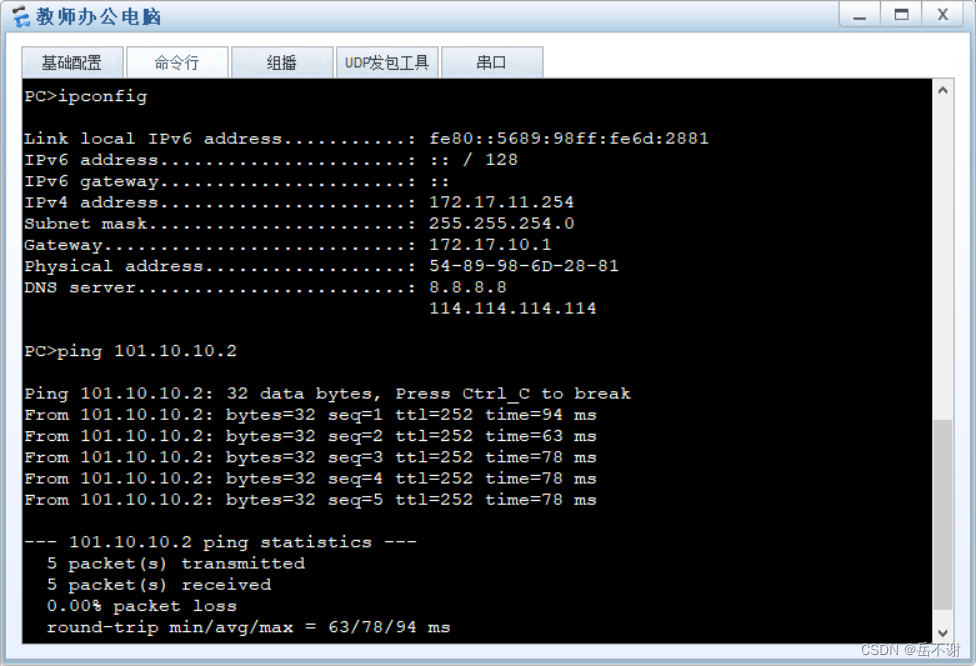
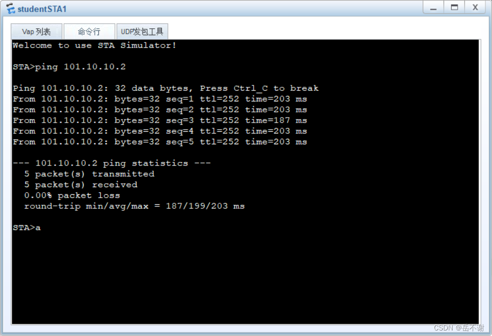
6.5配置外网访问DMZ
(1)使用外网的师生访问DMZ的教务系统
[USG6000V1]security-policy
rule name untrust_to_DMZ
source-zone untrust
destination-zone dmz
action permit
quit
[USG6000V1]nat server jiaowu_server global 112.10.10.1 inside 172.17.5.5 no-reverse
验证测试:
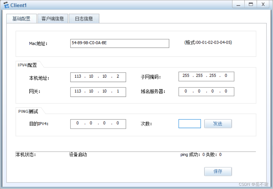
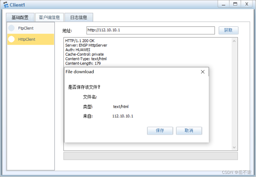
7.实验出现的问题
7.1本实验理论上可以实现ping通
一是实验会出现在其它区域出现ping不通,换另一台设备ping同一个地址又可以ping通;
二是配置环境可能因为设备太多,电脑性能带不起
7.2无线移动接入出现连接,一直获取不到IP地址的情况
可能是防火墙的原因,如果先启动防火墙,那么移动终端会出现无法接入AP,所以先把移动终端成功接入,再启动防火墙
7.3对于验证测试
验证测试的结果不一定在自己预想的情况实现ping通,环境的原因吧
最后,如有不足之处,请各位大神给予我一些指导意见,以及配置修正!!!


