- 1全国产化异构加速GPU服务器_国产gpu服务器
- 2Hive-拉链表的设计与实现
- 3拒绝庞大臃肿,快速建模智慧楼宇,实现运行轻量化_revit智慧公寓楼
- 4【写时复制(精华,从源码分析总结)】
- 5史上最全1000+Java高频面试合集,21个技术专题,命中率高达98%
- 6用docker定制odoo的镜像并运行容器的过程(纯手工制作)_odoo docker
- 7MySQL忘记root密码解决方法_mysql workbench 登录后怎样用sql 查询root对应 密码
- 8SQLite——世界上部署最广泛的免费开源数据库(简介)_sqllite本地数据库
- 9尚学堂第七章作业参考答案_public class exam2{ static void pass(string x){ x+
- 10MySQL IS NULL判断值是否为NULL及优化详解_mysql isnull
Linux ipvlan详解(l2、l3、l3s和bridge、private和vepa模式)_linux 网卡vlan模式
赞
踩
Linux ipvlan详解,测试l2、l3、l3s和bridge、private和vepa模式。
最近在看Docker的网络,看到关于ipvlan网络的介绍。查阅了相关资料,记录如下。
参考
1.图解几个与Linux网络虚拟化相关的虚拟网卡-VETH/MACVLAN/MACVTAP/IPVLAN
2.IPVlan 详解
3.IPVLAN Driver HOWTO
4.IPVlan 源码探秘
5.ipvlan内核代码流程
6.从 VLAN 到 IPVLAN: 聊聊虚拟网络设备及其在云原生中的应用
7.Linux网络协议栈6–ipvlan
8.ipvlan-l3s模式
环境
操作系统
Ubuntu22.04
kernel 5.15
1. IPVALN 介绍
本节内容参考 链接1、链接2 和 链接3
1.1 IPVLAN虚拟网卡技术
IPVLAN与MACVLAN类似。IPVLAN和MACVLAN的区别在于它在IP层进行流量分离而不是基于MAC地址,因此,你可以看到,同属于一块宿主以太网卡的所有IPVLAN虚拟网卡的MAC地址都是一样的,因为宿主以太网卡根本不是用MAC地址来分流IPVLAN虚拟网卡的流量的。具体的流程如下图所示:
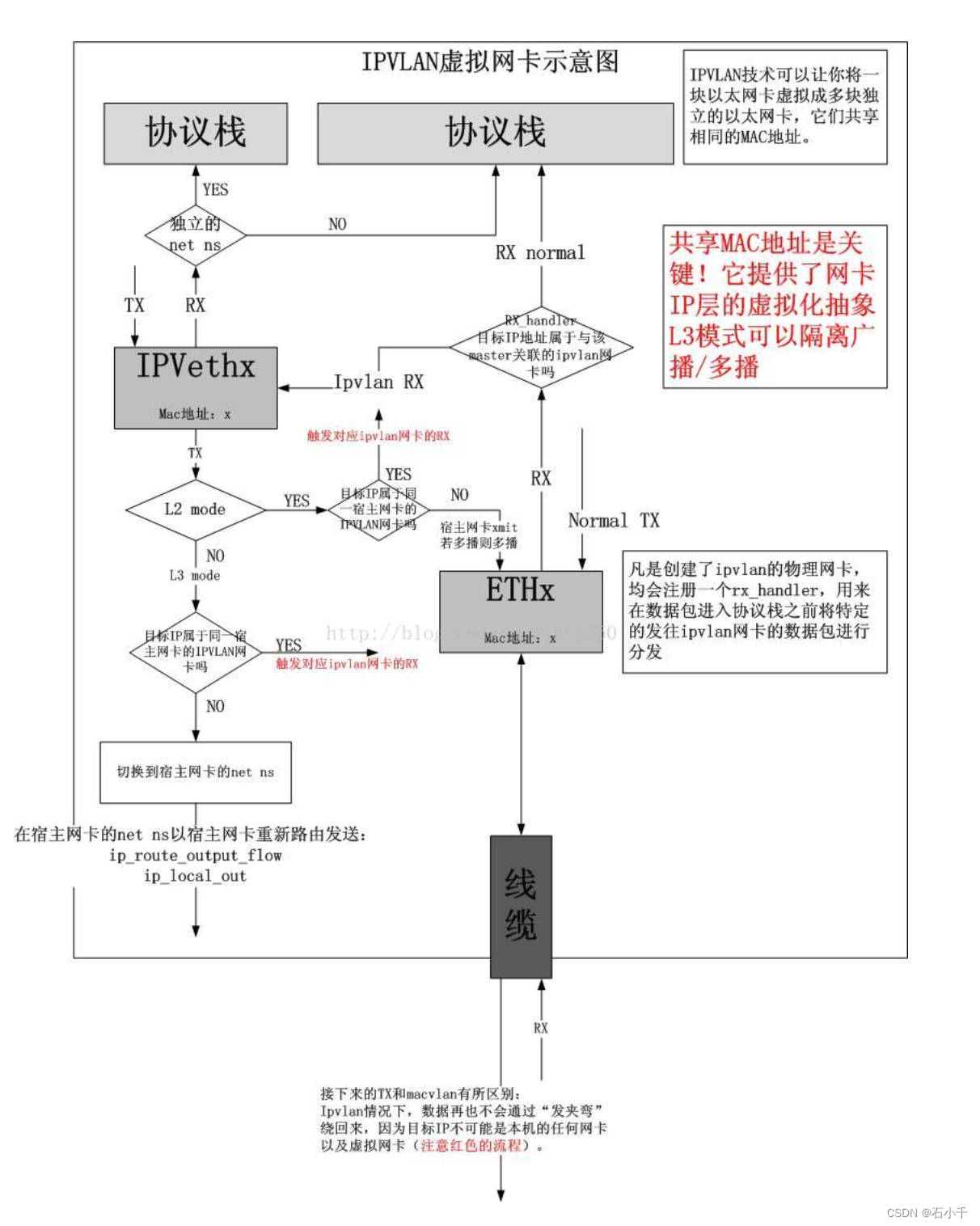
由于所有的虚拟接口共享同个mac地址,因此有些地方需要注意:当使用 DHCP 协议分配 ip 时,一般会用 mac 地址作为机器的标识,因此需要配置唯一的 ClientID 字段作为机器的标识, DHCP server 配置 ip 时需使用该字段作为机器标识,而不是使用 mac 地址。
1.2 三种模式(mode)
ipvlan 有三种不同的工作模式:L2 、L3 和 L3s。一个父接口只能选择其中一种模式(不能采用混用模式),依附于它的所有虚拟接口都会运行在这个模式下。
1、L2 模式
Ipvlan 的 L2 模式和 macvlan 的 bridge 模式工作原理很相似,父接口作为交换机来转发子接口的数据。同一个网络的子接口可以通过父接口来转发数据,而如果想发送到其他网络,报文则会通过父接口的路由转发出去。
2、L3 模式
L3 模式下,ipvlan 有点像路由器的功能,它在各个虚拟网络和主机网络之间进行不同网络报文的路由转发工作。只要父接口相同,即使虚拟机/容器不在同一个网络,也可以互相 ping 通对方,因为 ipvlan 会在中间做报文的转发工作。该模式把父接口当成一个路由器,完全不支持广播,这个模式下的接口也比l2模式下的ipvlan接口多了一个 NOARP属性,也不会发送广播报文
2、L3s 模式
L3s 模式下与L3 模式类似,区别在于启用了iptables (conn-tracking)
上述三种MODE不能混用。
4.1 L2 mode:
	In this mode TX processing happens on the stack instance attached to the
slave device and packets are switched and queued to the master device to send
out. In this mode the slaves will RX/TX multicast and broadcast (if applicable)
as well.

4.2 L3 mode:
	In this mode TX processing up to L3 happens on the stack instance attached
to the slave device and packets are switched to the stack instance of the
master device for the L2 processing and routing from that instance will be
used before packets are queued on the outbound device. In this mode the slaves
will not receive nor can send multicast / broadcast traffic.

4.3 L3S mode:
	This is very similar to the L3 mode except that iptables (conn-tracking)
works in this mode and hence it is L3-symmetric (L3s). This will have slightly less
performance but that shouldn't matter since you are choosing this mode over plain-L3
mode to make conn-tracking work.
- 1
- 2
- 3
- 4
- 5
- 6
- 7
- 8
- 9
- 10
- 11
- 12
- 13
- 14
- 15
- 16
- 17
- 18
1.3 三种FLAGS
ipvlan 有三种不同的flag:bridge 、private 和 vepa。bridge允许同一父接口下的子接口直接通讯;private禁止子接口之间通讯;vepa禁止子接口之间直接通讯,需要外部交换机开启hairpin(802.1q)转发通讯。
上述三种FLAG不能混用。
5. Mode flags:
	At this time following mode flags are available

5.1 bridge:
	This is the default option. To configure the IPvlan port in this mode,
user can choose to either add this option on the command-line or don't specify
anything. This is the traditional mode where slaves can cross-talk among
themselves apart from talking through the master device.

5.2 private:
	If this option is added to the command-line, the port is set in private
mode. i.e. port won't allow cross communication between slaves.

5.3 vepa:
	If this is added to the command-line, the port is set in VEPA mode.
i.e. port will offload switching functionality to the external entity as
described in 802.1Qbg
Note: VEPA mode in IPvlan has limitations. IPvlan uses the mac-address of the
master-device, so the packets which are emitted in this mode for the adjacent
neighbor will have source and destination mac same. This will make the switch /
router send the redirect message.
- 1
- 2
- 3
- 4
- 5
- 6
- 7
- 8
- 9
- 10
- 11
- 12
- 13
- 14
- 15
- 16
- 17
- 18
- 19
- 20
- 21
说明:IPVlan 和 MACVlan 会有各种模式(mode)和 flag,比如 bridge,VEPA(virtual ethernet port aggregator),private,passthrough。形象举例,假如父接口是一个聊天群,所有的群成员都可以向外发消息,那么可以这样理解:
- bridge 模式,所有群成员可以在群内发言。
- private 模式,所有群成员禁言的,既不能在群内发言,也不能在群外发言。
- vepa 模式,所有群成员在群内禁言,但是可以在群外互相私聊(需要外部交换支持802.1q)。
- passthrough 模式,只有群主可以发言,其他人禁言。
1.4 收发包流程
本节内容参考 链接2、链接5
1.4.1 收包流程
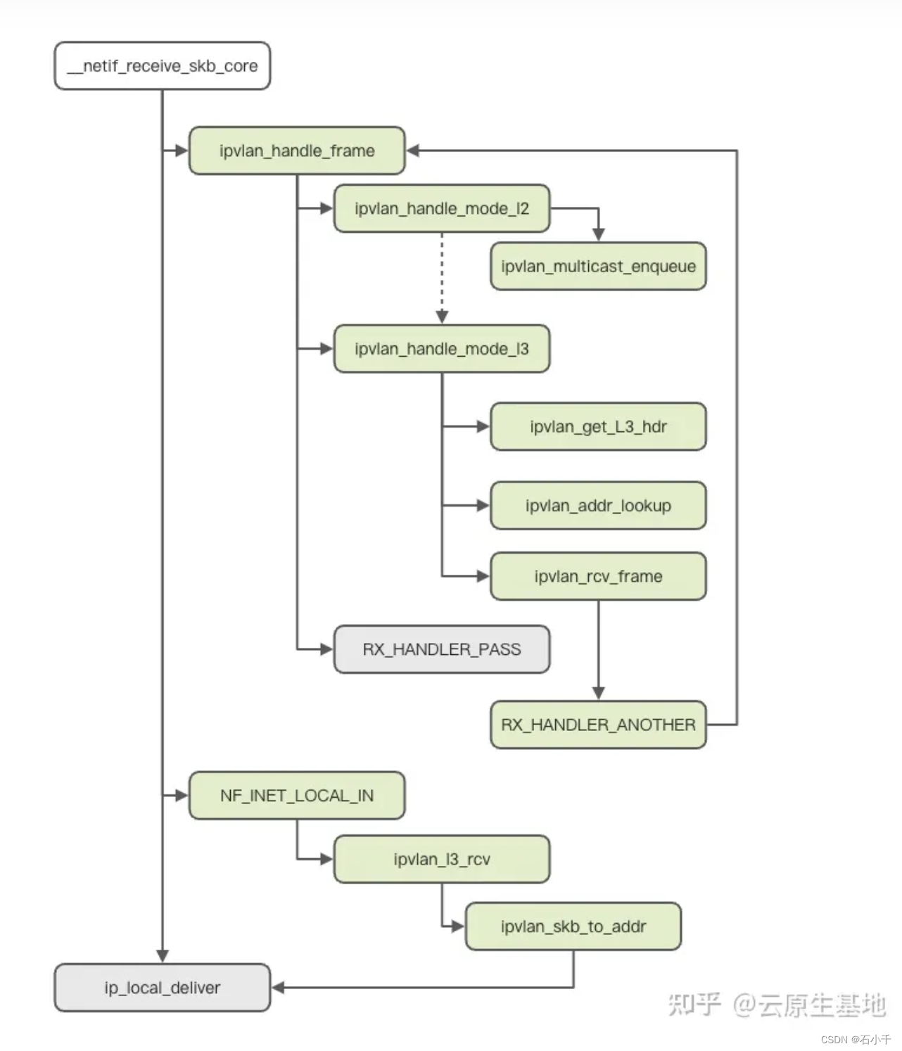 IPVlan 子设备的三种 mode 分别有不同的收包处理流程,在内核的流程如下:
首先会经过__netif_receive_skb_core 进入到创建时注册的 ipvlan_handle_frame 的处理流程,此时数据包依然是主设备所拥有。
rx_handler_result_t ipvlan_handle_frame(struct sk_buff **pskb)
{
	struct sk_buff *skb = *pskb;
	struct ipvl_port *port = ipvlan_port_get_rcu(skb->dev);

	if (!port)
		return RX_HANDLER_PASS;

	switch (port->mode) {
	case IPVLAN_MODE_L2:
		return ipvlan_handle_mode_l2(pskb, port);
	case IPVLAN_MODE_L3:
		return ipvlan_handle_mode_l3(pskb, port);
#ifdef CONFIG_IPVLAN_L3S
	case IPVLAN_MODE_L3S:
		return RX_HANDLER_PASS;
#endif
	}

	/* Should not reach here */
	WARN_ONCE(true, "%s called for mode = [%x]\n", __func__, port->mode);
	kfree_skb(skb);
	return RX_HANDLER_CONSUMED;
}
- 1
- 2
- 3
- 4
- 5
- 6
- 7
- 8
- 9
- 10
- 11
- 12
- 13
- 14
- 15
- 16
- 17
- 18
- 19
- 20
- 21
- 22
- 23
- 24
- ipvlan l2
对于 mode l2 模式的报文处理,只处理多播的报文,将报文放进前面创建子设备时初始化的多播处理的队列;对于单播报文,会直接交给 ipvlan_handle_mode_l3 进行处理!
static rx_handler_result_t ipvlan_handle_mode_l2(struct sk_buff **pskb,
						 struct ipvl_port *port)
{
	struct sk_buff *skb = *pskb;
	struct ethhdr *eth = eth_hdr(skb);
	rx_handler_result_t ret = RX_HANDLER_PASS;
	// 多播
	if (is_multicast_ether_addr(eth->h_dest)) {
		if (ipvlan_external_frame(skb, port)) {
			struct sk_buff *nskb = skb_clone(skb, GFP_ATOMIC);

			/* External frames are queued for device local
			 * distribution, but a copy is given to master
			 * straight away to avoid sending duplicates later
			 * when work-queue processes this frame. This is
			 * achieved by returning RX_HANDLER_PASS.
			 */
			if (nskb) {
				ipvlan_skb_crossing_ns(nskb, NULL);
				ipvlan_multicast_enqueue(port, nskb, false);
			}
		}
	// 单播
	} else {
		/* Perform like l3 mode for non-multicast packet */
		ret = ipvlan_handle_mode_l3(pskb, port);
	}

	return ret;
}
- 1
- 2
- 3
- 4
- 5
- 6
- 7
- 8
- 9
- 10
- 11
- 12
- 13
- 14
- 15
- 16
- 17
- 18
- 19
- 20
- 21
- 22
- 23
- 24
- 25
- 26
- 27
- 28
- 29
- 30
- ipvlan l3
对于 mode l3 或者单播的 mode l2 报文,进入 ipvlan_handle_mode_l3 处理流程,首先通过 ipvlan_get_L3_hdr 获取到网络层的头信息,然后根据 ip 地址去查找到对应的子设备,最后调用 ipvlan_rcv_frame,将报文的 dev 设置为 IPVlan 子设备并返回 RX_HANDLER_ANOTHER,进行下一次收包。
static rx_handler_result_t ipvlan_handle_mode_l3(struct sk_buff **pskb,
						 struct ipvl_port *port)
{
	void *lyr3h;
	int addr_type;
	struct ipvl_addr *addr;
	struct sk_buff *skb = *pskb;
	rx_handler_result_t ret = RX_HANDLER_PASS;

	lyr3h = ipvlan_get_L3_hdr(port, skb, &addr_type);
	if (!lyr3h)
		goto out;
	// 寻找目标地址子设备
	addr = ipvlan_addr_lookup(port, lyr3h, addr_type, true);
	if (addr)
		// 对应子设备收包
		ret = ipvlan_rcv_frame(addr, pskb, false);

out:
	// 走主设备路由
	return ret;
}
- 1
- 2
- 3
- 4
- 5
- 6
- 7
- 8
- 9
- 10
- 11
- 12
- 13
- 14
- 15
- 16
- 17
- 18
- 19
- 20
- 21
- 22
- ipvlan l3s
对于 mode l3s,在 ipvlan_handle_frame 中会直接返回 RX_HANDLER_PASS,也就是说,mode l3s 的报文会在主设备就进入到网络层的处理阶段,对于 mode l3s 来说,预先注册的 nf_hook 会在 NF_INET_LOCAL_IN 时触发,执行 ipvlan_l3_rcv 操作,通过 addr 找到子设备,更换报文的网络层目的地址,然后直接进入 ip_local_deliver 进行网络层余下的操作。
    case IPVLAN_MODE_L3S:
        return RX_HANDLER_PASS;
- 1
- 2
具体请参考:ipvlan-l3s模式
1.4.2 发包流程
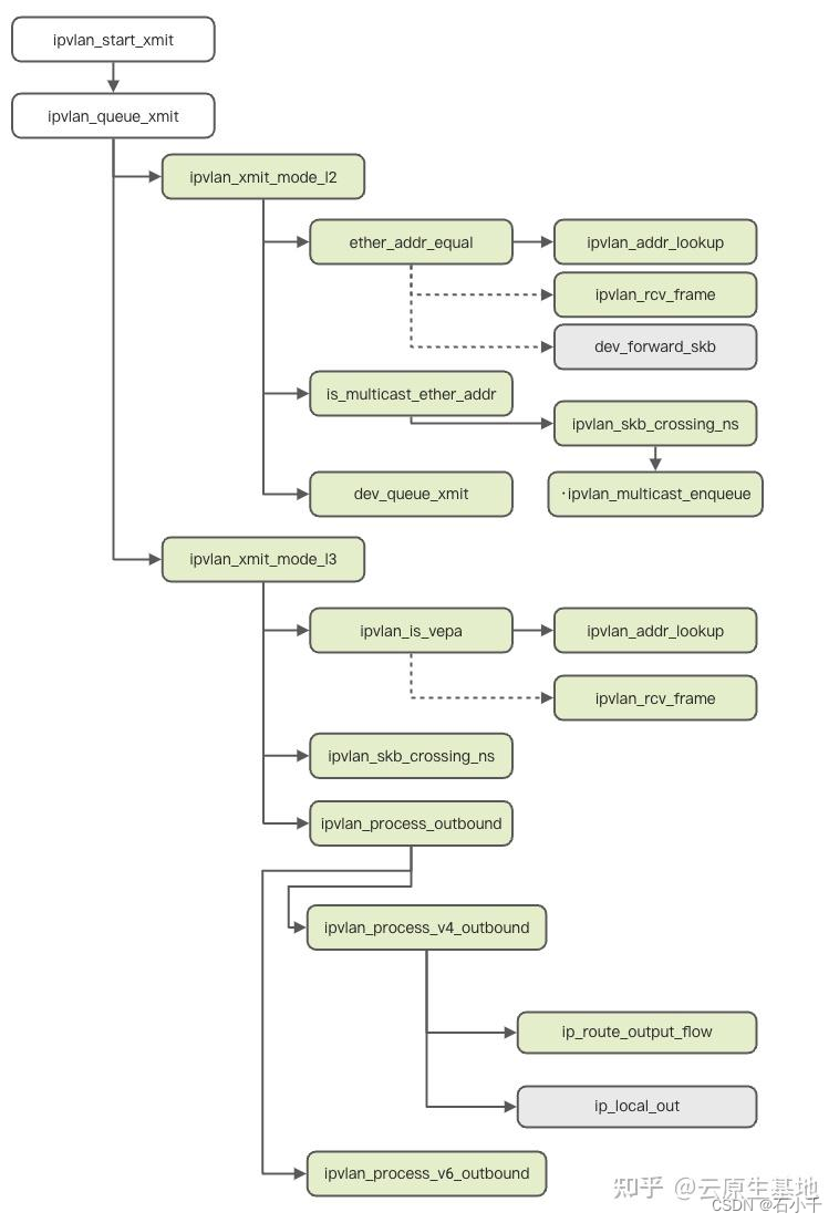
ipvlan_queue_xmit 根据子设备的模式选择不同的发送方法,mode l2 通过 ipvlan_xmit_mode_l2 发送,mode l3 和 mode l3s 进行 ipvlan_xmit_mode_l3 发送。
int ipvlan_queue_xmit(struct sk_buff *skb, struct net_device *dev)
{
	struct ipvl_dev *ipvlan = netdev_priv(dev);
	struct ipvl_port *port = ipvlan_port_get_rcu_bh(ipvlan->phy_dev);

	if (!port)
		goto out;

	if (unlikely(!pskb_may_pull(skb, sizeof(struct ethhdr))))
		goto out;

	switch(port->mode) {
	// l2
	case IPVLAN_MODE_L2:
		return ipvlan_xmit_mode_l2(skb, dev);
	// l3
	case IPVLAN_MODE_L3:
#ifdef CONFIG_IPVLAN_L3S
    // ls3
	case IPVLAN_MODE_L3S:
#endif
		return ipvlan_xmit_mode_l3(skb, dev);
	}

	/* Should not reach here */
	WARN_ONCE(true, "%s called for mode = [%x]\n", __func__, port->mode);
out:
	kfree_skb(skb);
	return NET_XMIT_DROP;
}
- 1
- 2
- 3
- 4
- 5
- 6
- 7
- 8
- 9
- 10
- 11
- 12
- 13
- 14
- 15
- 16
- 17
- 18
- 19
- 20
- 21
- 22
- 23
- 24
- 25
- 26
- 27
- 28
- 29
- 30
- ipvlan_xmit_mode_l2
1. 对于 ipvlan_xmit_mode_l2,首先判断是否是本地地址或者 VEPA 模式,如果不是 VEPA 模式的本地报文,则首先通过 ipvlan_addr_lookup 查找是否是相同主设备下的 IPVlan 子设备,如果是相同主设备下的 IPVlan 子设备,则通过 ipvlan_rcv_frame 让对应子设备进行收包处理;如果不是,则通过 dev_forward_skb 让主设备进行处理。
2. 接下来 ipvlan_xmit_mode_l2 会对多播报文进行处理,在处理之前,通过 ipvlan_skb_crossing_ns 清理掉数据包的 netns 相关的信息,包括 priority 等,最后将数据包放到 ipvlan_multicast_enqueue,触发上述的多播处理流程。
3. 对于非本地的数据包,通过主设备的 dev_queue_xmit 进行发送。
static int ipvlan_xmit_mode_l2(struct sk_buff *skb, struct net_device *dev)
{
	const struct ipvl_dev *ipvlan = netdev_priv(dev);
	struct ethhdr *eth = skb_eth_hdr(skb);
	struct ipvl_addr *addr;
	void *lyr3h;
	int addr_type;
	// ipvlan模式不是vepa 且 源mac 与 目标mac 相同
	if (!ipvlan_is_vepa(ipvlan->port) &&
	    ether_addr_equal(eth->h_dest, eth->h_source)) {
		lyr3h = ipvlan_get_L3_hdr(ipvlan->port, skb, &addr_type);
		if (lyr3h) {
		  // 寻找目标地址
			addr = ipvlan_addr_lookup(ipvlan->port, lyr3h, addr_type, true);
			if (addr) {
				// ipvlan模式是 private ,那么 drop
				if (ipvlan_is_private(ipvlan->port)) {
					consume_skb(skb);
					return NET_XMIT_DROP;
				}
				// 调用该目标地址的子设备收包
				ipvlan_rcv_frame(addr, &skb, true);
				return NET_XMIT_SUCCESS;
			}
		}
		skb = skb_share_check(skb, GFP_ATOMIC);
		if (!skb)
			return NET_XMIT_DROP;

		/* Packet definitely does not belong to any of the
		 * virtual devices, but the dest is local. So forward
		 * the skb for the main-dev. At the RX side we just return
		 * RX_PASS for it to be processed further on the stack.
		 */
		// 如果不属于子设备,直接送主设备处理
		dev_forward_skb(ipvlan->phy_dev, skb);
		return NET_XMIT_SUCCESS;
    // 处理多播包
	} else if (is_multicast_ether_addr(eth->h_dest)) {
		skb_reset_mac_header(skb);
		ipvlan_skb_crossing_ns(skb, NULL);
		ipvlan_multicast_enqueue(ipvlan->port, skb, true);
		return NET_XMIT_SUCCESS;
	}
  // 是vepa 或 源mac与目标mac不同,且不是多播包,直接送主设备发出
	skb->dev = ipvlan->phy_dev;
	return dev_queue_xmit(skb);
}
- 1
- 2
- 3
- 4
- 5
- 6
- 7
- 8
- 9
- 10
- 11
- 12
- 13
- 14
- 15
- 16
- 17
- 18
- 19
- 20
- 21
- 22
- 23
- 24
- 25
- 26
- 27
- 28
- 29
- 30
- 31
- 32
- 33
- 34
- 35
- 36
- 37
- 38
- 39
- 40
- 41
- 42
- 43
- 44
- 45
- 46
- 47
- 48
- ipvlan_xmit_mode_l3
1. ipvlan_xmit_mode_l3 的处理首先也是对 VEPA 进行判断,对于非 VEPA 模式的数据包,通过ipvlan_addr_lookup 查找是否是其他子设备,如果是其他子设备则调用 ipvlan_rcv_frame 触发对应子设备进行收包处理。
2. 对于 VEPA 模式或目标地址不是本地的数据包,首先进行 ipvlan_skb_crossing_ns 的处理,然后进行 ipvlan_process_outbound的操作,此时根据数据包的网络层协议,选择 ipvlan_process_v4_outbound 或者 ipvlan_process_v6_outbound 进行处理。
3. 以 ipvlan_process_v4_outbound 为例,首先会通过 ip_route_output_flow 进行路由的查找,然后直接通过网络层的 ip_local_out,在主设备的网络层继续进行发包操作。
static int ipvlan_xmit_mode_l3(struct sk_buff *skb, struct net_device *dev)
{
	const struct ipvl_dev *ipvlan = netdev_priv(dev);
	void *lyr3h;
	struct ipvl_addr *addr;
	int addr_type;

	lyr3h = ipvlan_get_L3_hdr(ipvlan->port, skb, &addr_type);
	if (!lyr3h)
		goto out;
	// 如果ipvlan模式不是vepa
	if (!ipvlan_is_vepa(ipvlan->port)) {
		// 寻找目标地址
		addr = ipvlan_addr_lookup(ipvlan->port, lyr3h, addr_type, true);
		// 如果找到了目标地址
		if (addr) {
			// 如果ipvlan模式是 private ,那么丢弃
			if (ipvlan_is_private(ipvlan->port)) {
				consume_skb(skb);
				return NET_XMIT_DROP;
			}
			// 只剩下bridge模式,调用该目标地址的子设备收包
			ipvlan_rcv_frame(addr, &skb, true);
			return NET_XMIT_SUCCESS;
		}
	}
out:
	// 是vepa 或 目标地址不是本子设备,交给主设备,ip_route_output_flow查找路由表,走三层转发
	ipvlan_skb_crossing_ns(skb, ipvlan->phy_dev);
	return ipvlan_process_outbound(skb);
}
- 1
- 2
- 3
- 4
- 5
- 6
- 7
- 8
- 9
- 10
- 11
- 12
- 13
- 14
- 15
- 16
- 17
- 18
- 19
- 20
- 21
- 22
- 23
- 24
- 25
- 26
- 27
- 28
- 29
- 30
- 31
2. IPVLAN 测试
注意: IPVLAN的mode(l2、l3、l3s)与flags(bridge、private、vepa)均不能混用。
2.1 创建 IPVLAN 命令
- Linux 创建 IPVLAN
root@ubuntu22-25:~# ip link add help
Usage: ip link add [link DEV | parentdev NAME] [ name ] NAME
                    [ txqueuelen PACKETS ]
                    [ address LLADDR ]
                    [ broadcast LLADDR ]
                    [ mtu MTU ] [index IDX ]
                    [ numtxqueues QUEUE_COUNT ]
                    [ numrxqueues QUEUE_COUNT ]
                    type TYPE [ ARGS ]
......

        ip link help [ TYPE ]

TYPE := { bareudp | bond | bond_slave | bridge | bridge_slave |
          dummy | erspan | geneve | gre | gretap | ifb |
          ip6erspan | ip6gre | ip6gretap | ip6tnl |
          ipip | ipoib | ipvlan | ipvtap |
          macsec | macvlan | macvtap |
          netdevsim | nlmon | rmnet | sit | team | team_slave |
          vcan | veth | vlan | vrf | vti | vxcan | vxlan | wwan |
          xfrm }
- 1
- 2
- 3
- 4
- 5
- 6
- 7
- 8
- 9
- 10
- 11
- 12
- 13
- 14
- 15
- 16
- 17
- 18
- 19
- 20
- 21
- IPVLAN 可选的 MODE 和 FLAGS
root@ubuntu22-25:~# ip link help ipvlan
Usage: ... ipvlan [ mode MODE ] [ FLAGS ]

MODE: l3 | l3s | l2
FLAGS: bridge | private | vepa
(first values are the defaults if nothing is specified).
root@ubuntu22-25:~#
- 1
- 2
- 3
- 4
- 5
- 6
- 7
2.2 测试 IPVLAN L2
2.2.1 IPVLAN l2 bridge 同父接口下子接口通讯情况
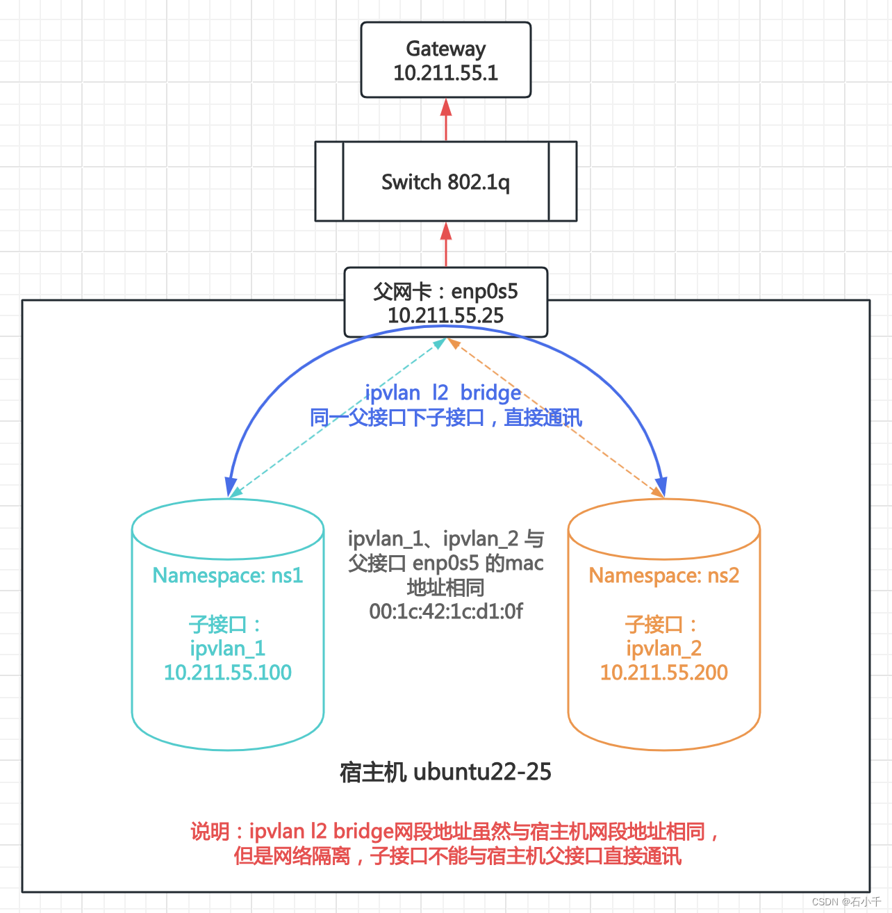
1.测试步骤:以enp0s5为父接口,创建两个ipvlan子接口,mode:l2、flags:bridge(ipvlan_1和ipvlan_2),分别加入到网络命名空间ns1和ns2中。在命名空间中配置两个ipvlan子接口IP(ipvlan_1 10.211.55.100,ipvlan_2 10.211.55.200)并启用。测试两个ipvlan子接口网络通讯情况,如下图:
2.测试结果: IPVLAN l2 bridge模式下,同一父接口下的子接口直接通讯
2.2.1.1 配置 IPVLAN l2 bridge 环境
- 查看当前网卡,enp0s5作为父接口
root@ubuntu22-25:~# ip a
1: lo: <LOOPBACK,UP,LOWER_UP> mtu 65536 qdisc noqueue state UNKNOWN group default qlen 1000
    link/loopback 00:00:00:00:00:00 brd 00:00:00:00:00:00
    inet 127.0.0.1/8 scope host lo
       valid_lft forever preferred_lft forever
    inet6 ::1/128 scope host
       valid_lft forever preferred_lft forever
2: enp0s5: <BROADCAST,MULTICAST,UP,LOWER_UP> mtu 1500 qdisc fq_codel state UP group default qlen 1000
    link/ether 00:1c:42:1c:d1:0f brd ff:ff:ff:ff:ff:ff
    inet 10.211.55.25/24 brd 10.211.55.255 scope global enp0s5
       valid_lft forever preferred_lft forever
    inet6 fdb2:2c26:f4e4:0:21c:42ff:fe1c:d10f/64 scope global dynamic mngtmpaddr noprefixroute
       valid_lft 2591731sec preferred_lft 604531sec
    inet6 fe80::21c:42ff:fe1c:d10f/64 scope link
       valid_lft forever preferred_lft forever
root@ubuntu22-25:~#
- 1
- 2
- 3
- 4
- 5
- 6
- 7
- 8
- 9
- 10
- 11
- 12
- 13
- 14
- 15
- 16
- 创建网络命名空间:ns1 和 ns2
root@ubuntu22-25:~# ip netns add ns1
root@ubuntu22-25:~# ip netns add ns2
root@ubuntu22-25:~# ip netns list
ns2
ns1
- 1
- 2
- 3
- 4
- 5
- 创建父接口enp0s5的两个ipvlan子接口:ipvlan_1 和 ipvlan_2
root@ubuntu22-25:~# ip link add link enp0s5 name ipvlan_1 type ipvlan mode l2 bridge
root@ubuntu22-25:~# ip link add link enp0s5 name ipvlan_2 type ipvlan mode l2 bridge
- 1
- 2
- ipvlan_1 加入 ns1,配置IP 10.211.55.100,启用
// ipvlan_1 加入 ns1
root@ubuntu22-25:~# ip link set ipvlan_1 netns ns1
// 配置IP
root@ubuntu22-25:~# ip netns exec ns1 ip addr add 10.211.55.100/24 dev ipvlan_1
root@ubuntu22-25:~# ip netns exec ns1 ip link set ipvlan_1 up
root@ubuntu22-25:~# ip netns exec ns1 ip link set lo up
// 查看配置结果
root@ubuntu22-25:~# ip netns exec ns1 ip a
1: lo: <LOOPBACK,UP,LOWER_UP> mtu 65536 qdisc noqueue state UNKNOWN group default qlen 1000
    link/loopback 00:00:00:00:00:00 brd 00:00:00:00:00:00
    inet 127.0.0.1/8 scope host lo
       valid_lft forever preferred_lft forever
    inet6 ::1/128 scope host
       valid_lft forever preferred_lft forever
4: ipvlan_1@if2: <BROADCAST,MULTICAST,UP,LOWER_UP> mtu 1500 qdisc noqueue state UNKNOWN group default qlen 1000
    link/ether 00:1c:42:1c:d1:0f brd ff:ff:ff:ff:ff:ff link-netnsid 0
    inet 10.211.55.100/24 scope global ipvlan_1
       valid_lft forever preferred_lft forever
    inet6 fdb2:2c26:f4e4:0:1c:4200:11c:d10f/64 scope global dynamic mngtmpaddr
       valid_lft 2591992sec preferred_lft 604792sec
    inet6 fe80::1c:4200:11c:d10f/64 scope link
       valid_lft forever preferred_lft forever
root@ubuntu22-25:~#
- 1
- 2
- 3
- 4
- 5
- 6
- 7
- 8
- 9
- 10
- 11
- 12
- 13
- 14
- 15
- 16
- 17
- 18
- 19
- 20
- 21
- 22
- 23
- ipvlan_2 加入 ns2,配置IP 10.211.55.200,启用
// ipvlan_2 加入 ns2
root@ubuntu22-25:~# ip link set ipvlan_2 netns ns2
// 配置IP
root@ubuntu22-25:~# ip netns exec ns2 ip addr add 10.211.55.200/24 dev ipvlan_2
root@ubuntu22-25:~# ip netns exec ns2 ip link set ipvlan_2 up
root@ubuntu22-25:~# ip netns exec ns2 ip link set lo up
// 查看配置结果
root@ubuntu22-25:~# ip netns exec ns2 ip a
1: lo: <LOOPBACK,UP,LOWER_UP> mtu 65536 qdisc noqueue state UNKNOWN group default qlen 1000
    link/loopback 00:00:00:00:00:00 brd 00:00:00:00:00:00
    inet 127.0.0.1/8 scope host lo
       valid_lft forever preferred_lft forever
    inet6 ::1/128 scope host
       valid_lft forever preferred_lft forever
5: ipvlan_2@if2: <BROADCAST,MULTICAST,UP,LOWER_UP> mtu 1500 qdisc noqueue state UNKNOWN group default qlen 1000
    link/ether 00:1c:42:1c:d1:0f brd ff:ff:ff:ff:ff:ff link-netnsid 0
    inet 10.211.55.200/24 scope global ipvlan_2
       valid_lft forever preferred_lft forever
    inet6 fdb2:2c26:f4e4:0:1c:4200:21c:d10f/64 scope global dynamic mngtmpaddr
       valid_lft 2591992sec preferred_lft 604792sec
    inet6 fe80::1c:4200:21c:d10f/64 scope link
       valid_lft forever preferred_lft forever
root@ubuntu22-25:~#
- 1
- 2
- 3
- 4
- 5
- 6
- 7
- 8
- 9
- 10
- 11
- 12
- 13
- 14
- 15
- 16
- 17
- 18
- 19
- 20
- 21
- 22
- 23
2.2.1.2 测试 IPVLAN l2 bridge 子网卡通讯情况
- 子接口ipvlan_1 Ping 子接口ipvlan_2,通
- 子接口ipvlan_1 Ping 外部网关,通
- 子接口ipvlan_1 Ping 父接口,不通
// 同一父接口下两个子接口,互相Ping,通
root@ubuntu22-25:~# ip netns exec ns1 ping 10.211.55.200 -c3
PING 10.211.55.200 (10.211.55.200): 56 data bytes
64 bytes from 10.211.55.200: icmp_seq=0 ttl=64 time=0.110 ms
64 bytes from 10.211.55.200: icmp_seq=1 ttl=64 time=0.074 ms
64 bytes from 10.211.55.200: icmp_seq=2 ttl=64 time=0.073 ms
--- 10.211.55.200 ping statistics ---
3 packets transmitted, 3 packets received, 0% packet loss
round-trip min/avg/max/stddev = 0.073/0.086/0.110/0.000 ms
// 子接口 Ping 外部网关,通
root@ubuntu22-25:~# ip netns exec ns1 ping 10.211.55.1 -c3
PING 10.211.55.1 (10.211.55.1): 56 data bytes
64 bytes from 10.211.55.1: icmp_seq=0 ttl=128 time=0.387 ms
64 bytes from 10.211.55.1: icmp_seq=1 ttl=128 time=0.446 ms
64 bytes from 10.211.55.1: icmp_seq=2 ttl=128 time=0.351 ms
--- 10.211.55.1 ping statistics ---
3 packets transmitted, 3 packets received, 0% packet loss
round-trip min/avg/max/stddev = 0.351/0.395/0.446/0.039 ms
// 子接口与父接口隔离, Ping 父接口IP,不通
root@ubuntu22-25:~# ip netns exec ns1 ping 10.211.55.25 -c3
PING 10.211.55.25 (10.211.55.25): 56 data bytes
92 bytes from 10.211.55.100: Destination Host Unreachable
92 bytes from 10.211.55.100: Destination Host Unreachable
92 bytes from 10.211.55.100: Destination Host Unreachable
--- 10.211.55.25 ping statistics ---
3 packets transmitted, 0 packets received, 100% packet loss
root@ubuntu22-25:~#
- 1
- 2
- 3
- 4
- 5
- 6
- 7
- 8
- 9
- 10
- 11
- 12
- 13
- 14
- 15
- 16
- 17
- 18
- 19
- 20
- 21
- 22
- 23
- 24
- 25
- 26
- 27
2.2.2 IPVLAN l2 private 同父接口下子接口通讯情况
1.测试步骤:以enp0s5为父接口,创建两个ipvlan子接口,mode:l2、flags:private(eth_private1和eth_private2),分别加入到网络命名空间ns_private1和ns_private2中。在命名空间中配置两个ipvlan子接口IP(eth_private1 10.211.55.100,eth_private2 10.211.55.200)并启用。测试两个ipvlan子接口网络通讯情况,如下图:
2.测试结果: IPVLAN l2 private模式下,同一父接口下的子接口网络隔离,不能通讯
补充:ipvlan l2 private 模式下,同父接口下子接口之间数据包直接drop。详见上述 ”1.4.2 发包流程” 代码
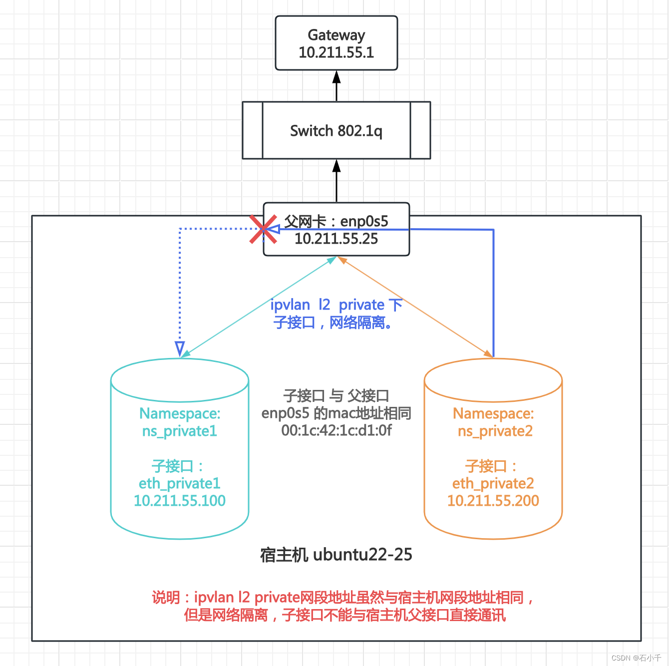
2.2.2.1 配置 IPVLAN l2 private 环境
- 创建父接口enp0s5的两个ipvlan子接口:eth_private1 和 eth_private2
root@ubuntu22-25:~# ip link add link enp0s5 name eth_private1 type ipvlan mode l2 private
root@ubuntu22-25:~# ip link add link enp0s5 name eth_private2 type ipvlan mode l2 private
- 1
- 2
- 创建网络命名空间:ns_private1 和 ns_private2
root@ubuntu22-25:~# ip netns add ns_private1
root@ubuntu22-25:~# ip netns add ns_private2
- 1
- 2
- eth_private1加入ns_private1,配置IP 10.211.55.100,并启用
// eth_private1加入ns_private1
root@ubuntu22-25:~# ip link set eth_private1 netns ns_private1
// 配置IP
root@ubuntu22-25:~# ip netns exec ns_private1 ip addr add 10.211.55.100/24 dev eth_private1
root@ubuntu22-25:~# ip netns exec ns_private1 ip link set eth_private1 up
root@ubuntu22-25:~# ip netns exec ns_private1 ip link set lo  up
// 查看配置结果
root@ubuntu22-25:~# ip netns exec ns_private1 ip a
1: lo: <LOOPBACK,UP,LOWER_UP> mtu 65536 qdisc noqueue state UNKNOWN group default qlen 1000
    link/loopback 00:00:00:00:00:00 brd 00:00:00:00:00:00
    inet 127.0.0.1/8 scope host lo
       valid_lft forever preferred_lft forever
    inet6 ::1/128 scope host
       valid_lft forever preferred_lft forever
3: eth_private1@if2: <BROADCAST,MULTICAST,UP,LOWER_UP> mtu 1500 qdisc noqueue state UNKNOWN group default qlen 1000
    link/ether 00:1c:42:1c:d1:0f brd ff:ff:ff:ff:ff:ff link-netnsid 0
    inet 10.211.55.100/24 scope global eth_private1
       valid_lft forever preferred_lft forever
    inet6 fdb2:2c26:f4e4:0:1c:4200:11c:d10f/64 scope global dynamic mngtmpaddr
       valid_lft 2591954sec preferred_lft 604754sec
    inet6 fe80::1c:4200:11c:d10f/64 scope link
       valid_lft forever preferred_lft forever
- 1
- 2
- 3
- 4
- 5
- 6
- 7
- 8
- 9
- 10
- 11
- 12
- 13
- 14
- 15
- 16
- 17
- 18
- 19
- 20
- 21
- 22
- eth_private2加入ns_private2,配置IP 10.211.55.200,并启用
// eth_private2加入ns_private2
root@ubuntu22-25:~# ip link set eth_private2 netns ns_private2
// 配置IP
root@ubuntu22-25:~# ip netns exec ns_private2 ip addr add 10.211.55.200/24 dev eth_private2
root@ubuntu22-25:~# ip netns exec ns_private2 ip link set eth_private2 up
root@ubuntu22-25:~# ip netns exec ns_private2 ip link set lo up
// 查看配置结果
root@ubuntu22-25:~# ip netns exec ns_private2 ip a
1: lo: <LOOPBACK,UP,LOWER_UP> mtu 65536 qdisc noqueue state UNKNOWN group default qlen 1000
    link/loopback 00:00:00:00:00:00 brd 00:00:00:00:00:00
    inet 127.0.0.1/8 scope host lo
       valid_lft forever preferred_lft forever
    inet6 ::1/128 scope host
       valid_lft forever preferred_lft forever
4: eth_private2@if2: <BROADCAST,MULTICAST,UP,LOWER_UP> mtu 1500 qdisc noqueue state UNKNOWN group default qlen 1000
    link/ether 00:1c:42:1c:d1:0f brd ff:ff:ff:ff:ff:ff link-netnsid 0
    inet 10.211.55.200/24 scope global eth_private2
       valid_lft forever preferred_lft forever
    inet6 fdb2:2c26:f4e4:0:1c:4200:21c:d10f/64 scope global dynamic mngtmpaddr
       valid_lft 2592000sec preferred_lft 604800sec
    inet6 fe80::1c:4200:21c:d10f/64 scope link
       valid_lft forever preferred_lft forever
root@ubuntu22-25:~#
- 1
- 2
- 3
- 4
- 5
- 6
- 7
- 8
- 9
- 10
- 11
- 12
- 13
- 14
- 15
- 16
- 17
- 18
- 19
- 20
- 21
- 22
- 23
2.2.2.2 测试 IPVLAN l2 private 子网卡通讯情况
- eth_private2 Ping 外部网关,通
- eth_private2 Ping eth_private1,private模式下,不通
- ipvlan子接口eth_private2 Ping 父接口(enp0s5),不通
// eth_private2 Ping 外部网关,通
root@ubuntu22-25:~# ip netns exec ns_private2 ping 10.211.55.1 -c3
PING 10.211.55.1 (10.211.55.1): 56 data bytes
64 bytes from 10.211.55.1: icmp_seq=0 ttl=128 time=0.355 ms
64 bytes from 10.211.55.1: icmp_seq=1 ttl=128 time=0.368 ms
64 bytes from 10.211.55.1: icmp_seq=2 ttl=128 time=0.369 ms
--- 10.211.55.1 ping statistics ---
3 packets transmitted, 3 packets received, 0% packet loss
round-trip min/avg/max/stddev = 0.355/0.364/0.369/0.000 ms
// eth_private2 Ping eth_private1,不通
root@ubuntu22-25:~# ip netns exec ns_private2 ping 10.211.55.100 -c3
PING 10.211.55.100 (10.211.55.100): 56 data bytes
92 bytes from 10.211.55.200: Destination Host Unreachable
92 bytes from 10.211.55.200: Destination Host Unreachable
92 bytes from 10.211.55.200: Destination Host Unreachable
--- 10.211.55.100 ping statistics ---
3 packets transmitted, 0 packets received, 100% packet loss
// 子接口eth_private2 Ping 父接口enp0s5,不通
root@ubuntu22-25:~# ip netns exec ns_private2 ping 10.211.55.25 -c3
PING 10.211.55.25 (10.211.55.25): 56 data bytes
92 bytes from 10.211.55.200: Destination Host Unreachable
92 bytes from 10.211.55.200: Destination Host Unreachable
92 bytes from 10.211.55.200: Destination Host Unreachable
--- 10.211.55.25 ping statistics ---
3 packets transmitted, 0 packets received, 100% packet loss
- 1
- 2
- 3
- 4
- 5
- 6
- 7
- 8
- 9
- 10
- 11
- 12
- 13
- 14
- 15
- 16
- 17
- 18
- 19
- 20
- 21
- 22
- 23
- 24
- 25
2.2.3 IPVLAN l2 vepa 同父接口下子接口通讯情况
1.测试步骤:创建一个Linux bridge(br0)和一对虚拟网卡veth1、veth1_br。veth1_br加入br0,用于控制开启关闭hairpin功能。veth1作为父接口(主设备)创建两个ipvlan子接口,mode:l2、flags:vepa(eth_vepa1和eth_vepa2),分别加入到网络命名空间ns_vepa1和ns_vepa2中。在命名空间中配置两个ipvlan子接口IP(eth_vepa1 10.211.55.100,eth_vepa2 10.211.55.200)并启用。测试两个ipvlan子接口网络通讯的情况,如下图。
2.测试结果:IPVLAN l2 vepa模式下,外部交换br0开启hairpin(支持802.1gbg)功能时,同一父接口下的子接口可以经外部交换转发通讯
补充:ipvlan l2 vepa 模式下,子接口数据包由父接口直接外发。详见上述 ”1.4.2 发包流程” 代码
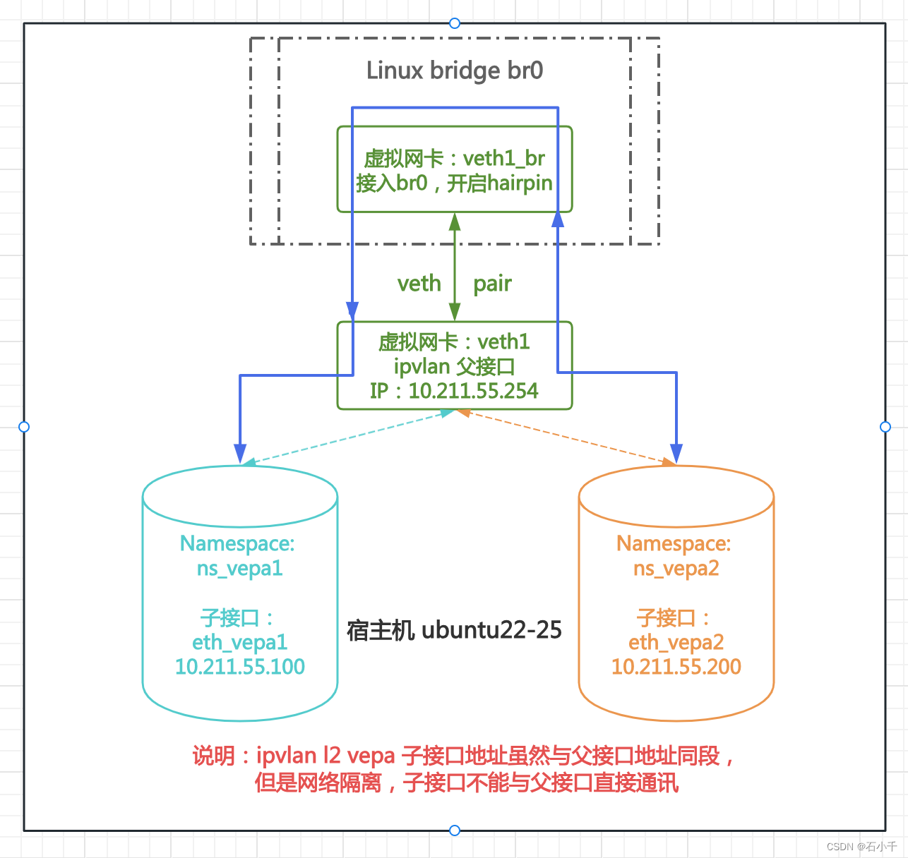
2.2.3.1 配置 Linux bridge 和 Veth pair
- 创建Linux bridge br0
- 创建veth pair:veth1和veth1_br
- veth1_br加入br0
// 创建Linux bridge br0,并启用
root@ubuntu22-25:~# brctl addbr br0
root@ubuntu22-25:~# ip link set br0 up
// 创建veth pair:veth1和veth1_br,并启用
root@ubuntu22-25:~# ip link add veth1 type veth peer veth1_br
root@ubuntu22-25:~# ip link set veth1 up
root@ubuntu22-25:~# ip link set veth1_br up
// veth1_br加入br0
root@ubuntu22-25:~# brctl addif br0 veth1_br
root@ubuntu22-25:~# brctl show
bridge name     bridge id               STP enabled     interfaces
br0             8000.ca19426b60e5       no              veth1_br
root@ubuntu22-25:~#
- 1
- 2
- 3
- 4
- 5
- 6
- 7
- 8
- 9
- 10
- 11
- 12
- 13
- 父接口veth1,配置IP 10.211.55.254
root@ubuntu22-25:~# ip addr add 10.211.55.254/24 dev veth1
root@ubuntu22-25:~# ip addr show veth1
5: veth1@veth1_br: <BROADCAST,MULTICAST,UP,LOWER_UP> mtu 1500 qdisc noqueue state UP group default qlen 1000
    link/ether 9a:72:89:8d:28:29 brd ff:ff:ff:ff:ff:ff
    inet 10.211.55.254/24 scope global veth1
       valid_lft forever preferred_lft forever
    inet6 fe80::9872:89ff:fe8d:2829/64 scope link
       valid_lft forever preferred_lft forever
root@ubuntu22-25:~#
- 1
- 2
- 3
- 4
- 5
- 6
- 7
- 8
- 9
2.2.3.2 配置 IPVLAN l2 vepa 环境
- 创建父接口veth1的两个ipvlan子接口:eth_vepa1 和 eth_vepa2
root@ubuntu22-25:~# ip link add link veth1 name eth_vepa1 type ipvlan mode l2 vepa
root@ubuntu22-25:~# ip link add link veth1 name eth_vepa2 type ipvlan mode l2 vepa
- 1
- 2
- 创建网络命名空间:ns_vepa1和ns_vepa2
root@ubuntu22-25:~# ip netns add ns_vepa1
root@ubuntu22-25:~# ip netns add ns_vepa2
- 1
- 2
- eth_vepa1加入ns_vepa1,配置IP 10.211.55.100,并启用
root@ubuntu22-25:~# ip link set eth_vepa1 netns ns_vepa1
root@ubuntu22-25:~# ip netns exec ns_vepa1 ip addr add 10.211.55.100/24 dev eth_vepa1
root@ubuntu22-25:~# ip netns exec ns_vepa1 ip link set eth_vepa1 up
root@ubuntu22-25:~# ip netns exec ns_vepa1 ip link set lo up
// 查看配置结果
root@ubuntu22-25:~# ip netns exec ns_vepa1 ip a
1: lo: <LOOPBACK,UP,LOWER_UP> mtu 65536 qdisc noqueue state UNKNOWN group default qlen 1000
    link/loopback 00:00:00:00:00:00 brd 00:00:00:00:00:00
    inet 127.0.0.1/8 scope host lo
       valid_lft forever preferred_lft forever
    inet6 ::1/128 scope host
       valid_lft forever preferred_lft forever
6: eth_vepa1@if5: <BROADCAST,MULTICAST,UP,LOWER_UP> mtu 1500 qdisc noqueue state UNKNOWN group default qlen 1000
    link/ether 9a:72:89:8d:28:29 brd ff:ff:ff:ff:ff:ff link-netnsid 0
    inet 10.211.55.100/24 scope global eth_vepa1
       valid_lft forever preferred_lft forever
    inet6 fe80::9a72:8900:18d:2829/64 scope link
       valid_lft forever preferred_lft forever
- 1
- 2
- 3
- 4
- 5
- 6
- 7
- 8
- 9
- 10
- 11
- 12
- 13
- 14
- 15
- 16
- 17
- 18
- eth_vepa2加入ns_vepa2,配置IP 10.211.55.200,并启用
root@ubuntu22-25:~# ip link set eth_vepa2 netns ns_vepa2
root@ubuntu22-25:~# ip netns exec ns_vepa2 ip addr add 10.211.55.200/24 dev eth_vepa2
root@ubuntu22-25:~# ip netns exec ns_vepa2 ip link set eth_vepa2 up
root@ubuntu22-25:~# ip netns exec ns_vepa2 ip link set lo up
// 查看配置结果
root@ubuntu22-25:~# ip netns exec ns_vepa2 ip a
1: lo: <LOOPBACK,UP,LOWER_UP> mtu 65536 qdisc noqueue state UNKNOWN group default qlen 1000
    link/loopback 00:00:00:00:00:00 brd 00:00:00:00:00:00
    inet 127.0.0.1/8 scope host lo
       valid_lft forever preferred_lft forever
    inet6 ::1/128 scope host
       valid_lft forever preferred_lft forever
7: eth_vepa2@if5: <BROADCAST,MULTICAST,UP,LOWER_UP> mtu 1500 qdisc noqueue state UNKNOWN group default qlen 1000
    link/ether 9a:72:89:8d:28:29 brd ff:ff:ff:ff:ff:ff link-netnsid 0
    inet 10.211.55.200/24 scope global eth_vepa2
       valid_lft forever preferred_lft forever
    inet6 fe80::9a72:8900:28d:2829/64 scope link
       valid_lft forever preferred_lft forever
- 1
- 2
- 3
- 4
- 5
- 6
- 7
- 8
- 9
- 10
- 11
- 12
- 13
- 14
- 15
- 16
- 17
- 18
2.2.3.3 测试 IPVLAN l2 vepa 子网卡通讯情况
- br0的接口veth1_br hairpin功能off
// 查看 bridge,veth1_br接口 hairpin off
root@ubuntu22-25:~# bridge -d link
3: br0: <BROADCAST,MULTICAST,UP,LOWER_UP> mtu 1500 master br0
4: veth1_br@veth1: <BROADCAST,MULTICAST,UP,LOWER_UP> mtu 1500 master br0 state forwarding priority 32 cost 2
    hairpin off guard off root_block off fastleave off learning on flood on mcast_flood on mcast_to_unicast off neigh_suppress off vlan_tunnel off isolated off
root@ubuntu22-25:~#
- 1
- 2
- 3
- 4
- 5
- 6
- eth_vepa2 Ping eth_vepa1,vepa模式下,不通
root@ubuntu22-25:~# ip netns exec ns_vepa2 ping 10.211.55.100 -c3
PING 10.211.55.100 (10.211.55.100): 56 data bytes
--- 10.211.55.100 ping statistics ---
3 packets transmitted, 0 packets received, 100% packet loss
root@ubuntu22-25:~#
- 1
- 2
- 3
- 4
- 5
- br0的接口veth1_br 开启hairpin功能
root@ubuntu22-25:~# brctl hairpin br0 veth1_br on
root@ubuntu22-25:~# bridge -d link
3: br0: <BROADCAST,MULTICAST,UP,LOWER_UP> mtu 1500 master br0
4: veth1_br@veth1: <BROADCAST,MULTICAST,UP,LOWER_UP> mtu 1500 master br0 state forwarding priority 32 cost 2
    hairpin on guard off root_block off fastleave off learning on flood on mcast_flood on mcast_to_unicast off neigh_suppress off vlan_tunnel off isolated off
- 1
- 2
- 3
- 4
- 5
- eth_vepa2 Ping eth_vepa1,vepa模式下,通
通过外部开启hairpin功能的 br0 实现转发
root@ubuntu22-25:~# ip netns exec ns_vepa2 ping 10.211.55.100 -c3
PING 10.211.55.100 (10.211.55.100): 56 data bytes
64 bytes from 10.211.55.100: icmp_seq=0 ttl=64 time=0.124 ms
64 bytes from 10.211.55.100: icmp_seq=1 ttl=64 time=0.083 ms
64 bytes from 10.211.55.100: icmp_seq=2 ttl=64 time=0.091 ms
--- 10.211.55.100 ping statistics ---
3 packets transmitted, 3 packets received, 0% packet loss
round-trip min/avg/max/stddev = 0.083/0.099/0.124/0.000 ms
- 1
- 2
- 3
- 4
- 5
- 6
- 7
- 8
- 子接口eth_vepa2 Ping 父接口,不通
root@ubuntu22-25:~# ip netns exec ns_vepa2 ping 10.211.55.254 -c3
PING 10.211.55.254 (10.211.55.254): 56 data bytes
92 bytes from 10.211.55.200: Destination Host Unreachable
92 bytes from 10.211.55.200: Destination Host Unreachable
92 bytes from 10.211.55.200: Destination Host Unreachable
--- 10.211.55.254 ping statistics ---
3 packets transmitted, 0 packets received, 100% packet loss
- 1
- 2
- 3
- 4
- 5
- 6
- 7
2.2.4 IPVLAN l2 bridge子接口与父接口通讯情况
1.测试步骤:在父接口enp0s5(10.211.55.25)下创建两个ipvlan子接口,mode:l2、flags:bridge(iplv2_bridge1和iplv2_bridge2),其中子接口iplv2_bridge1加入到网络命名空间ns1,配置IP(10.211.55.100)并启用;子接口iplv2_bridge2与父接口在相同网络命名空间中,配置与父接口同段IP(10.211.55.254)并启用。测试子接口iplv2_bridge1与父接口enp0s5网络通讯情况,如下图:
2.测试结果:IPVLAN l2 bridge模式下,父接口与子接口网络隔离,不能直接通讯,但是子接口可以通过与父接口同网络命名空间下的其它子接口转发通讯
补充:vepa与private模式下,ipvlan子接口之间无法直接通讯,无法实现中转
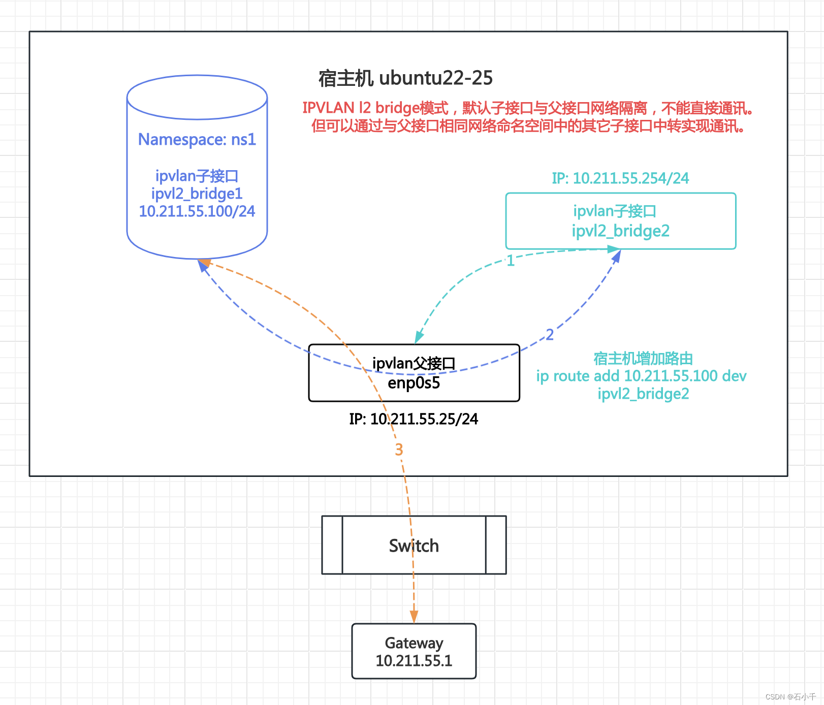
2.2.4.1 配置IPVLAN l2 bridge 子接口与父接口通讯环境
- 创建网络命名空间ns1
root@ubuntu22-25:~# ip netns add ns1
- 1
- 创建两个ipvlan子接口,mode l2,flags bridge:ipvl2_bridge1 和 ipvl2_bridge2
root@ubuntu22-25:~# ip link add link enp0s5 name ipvl2_bridge1 type ipvlan mode l2 bridge
root@ubuntu22-25:~#
root@ubuntu22-25:~# ip link add link enp0s5 name ipvl2_bridge2 type ipvlan mode l2 bridge
- 1
- 2
- 3
- 配置ipvlan子接口ipvl2_bridge1,并启用
- ipvl2_bridge1加入ns1
- 配置IP 10.211.55.100/24
// ipvl2_bridge1加入ns1
root@ubuntu22-25:~# ip link set ipvl2_bridge1 netns ns1
// 配置IP
root@ubuntu22-25:~# ip netns  exec ns1 ip addr add 10.211.55.100/24 dev  ipvl2_bridge1
root@ubuntu22-25:~# ip netns exec ns1 ip link set ipvl2_bridge1 up
root@ubuntu22-25:~# ip netns exec ns1 ip link set lo up
- 1
- 2
- 3
- 4
- 5
- 6
// 查看配置结果
root@ubuntu22-25:~# ip netns exec ns1 ip a
1: lo: <LOOPBACK,UP,LOWER_UP> mtu 65536 qdisc noqueue state UNKNOWN group default qlen 1000
    link/loopback 00:00:00:00:00:00 brd 00:00:00:00:00:00
    inet 127.0.0.1/8 scope host lo
       valid_lft forever preferred_lft forever
    inet6 ::1/128 scope host
       valid_lft forever preferred_lft forever
3: ipvl2_bridge1@if2: <BROADCAST,MULTICAST,UP,LOWER_UP> mtu 1500 qdisc noqueue state UNKNOWN group default qlen 1000
    link/ether 00:1c:42:1c:d1:0f brd ff:ff:ff:ff:ff:ff link-netnsid 0
    inet 10.211.55.100/24 scope global ipvl2_bridge1
       valid_lft forever preferred_lft forever
    inet6 fdb2:2c26:f4e4:0:1c:4200:11c:d10f/64 scope global dynamic mngtmpaddr
       valid_lft 2591959sec preferred_lft 604759sec
    inet6 fe80::1c:4200:11c:d10f/64 scope link
       valid_lft forever preferred_lft forever
- 1
- 2
- 3
- 4
- 5
- 6
- 7
- 8
- 9
- 10
- 11
- 12
- 13
- 14
- 15
- 16
- 配置ipvlan子接口ipvl2_bridge2,并启用
- 配置IP 10.211.55.254/24,与父接口在同一命名空间且IP地址段相同
// 配置IP
root@ubuntu22-25:~# ip addr add 10.211.55.254/24 dev ipvl2_bridge2
root@ubuntu22-25:~# ip link set ipvl2_bridge2 up
// 查看所有网卡IP
root@ubuntu22-25:~# ip a
1: lo: <LOOPBACK,UP,LOWER_UP> mtu 65536 qdisc noqueue state UNKNOWN group default qlen 1000
    link/loopback 00:00:00:00:00:00 brd 00:00:00:00:00:00
    inet 127.0.0.1/8 scope host lo
       valid_lft forever preferred_lft forever
    inet6 ::1/128 scope host
       valid_lft forever preferred_lft forever
2: enp0s5: <BROADCAST,MULTICAST,UP,LOWER_UP> mtu 1500 qdisc fq_codel state UP group default qlen 1000
    link/ether 00:1c:42:1c:d1:0f brd ff:ff:ff:ff:ff:ff
    inet 10.211.55.25/24 brd 10.211.55.255 scope global enp0s5
       valid_lft forever preferred_lft forever
    inet6 fdb2:2c26:f4e4:0:21c:42ff:fe1c:d10f/64 scope global dynamic mngtmpaddr noprefixroute
       valid_lft 2591632sec preferred_lft 604432sec
    inet6 fe80::21c:42ff:fe1c:d10f/64 scope link
       valid_lft forever preferred_lft forever
4: ipvl2_bridge2@enp0s5: <BROADCAST,MULTICAST,UP,LOWER_UP> mtu 1500 qdisc noqueue state UNKNOWN group default qlen 1000
    link/ether 00:1c:42:1c:d1:0f brd ff:ff:ff:ff:ff:ff
    inet 10.211.55.254/24 scope global ipvl2_bridge2
       valid_lft forever preferred_lft forever
    inet6 fe80::1c:4200:21c:d10f/64 scope link
       valid_lft forever preferred_lft forever
- 1
- 2
- 3
- 4
- 5
- 6
- 7
- 8
- 9
- 10
- 11
- 12
- 13
- 14
- 15
- 16
- 17
- 18
- 19
- 20
- 21
- 22
- 23
- 24
- 25
2.2.4.2 测试IPVLAN l2 bridge 子接口与父接口通讯
- ipvlan子接口ipvl2_bridge1经父接口enp0s5与外部网关通讯
- ns1下ipvl2_bridge1(10.211.55.100) Ping 外部网关(10.211.55.1),通
root@ubuntu22-25:~# ip netns exec ns1 ping 10.211.55.1 -c2
PING 10.211.55.1 (10.211.55.1): 56 data bytes
64 bytes from 10.211.55.1: icmp_seq=0 ttl=128 time=0.363 ms
64 bytes from 10.211.55.1: icmp_seq=1 ttl=128 time=0.209 ms
--- 10.211.55.1 ping statistics ---
2 packets transmitted, 2 packets received, 0% packet loss
round-trip min/avg/max/stddev = 0.209/0.286/0.363/0.077 ms
root@ubuntu22-25:~#
- 1
- 2
- 3
- 4
- 5
- 6
- 7
- 8
- ipvlan子接口ipvl2_bridge1不能与父接口enp0s5直接通讯
- ns1下ipvl2_bridge1(10.211.55.100)Ping 父接口(10.211.55.25),不通
root@ubuntu22-25:~# ip netns exec ns1 ping 10.211.55.25 -c3
PING 10.211.55.25 (10.211.55.25): 56 data bytes
92 bytes from 10.211.55.100: Destination Host Unreachable
92 bytes from 10.211.55.100: Destination Host Unreachable
92 bytes from 10.211.55.100: Destination Host Unreachable
--- 10.211.55.25 ping statistics ---
3 packets transmitted, 0 packets received, 100% packet loss
- 1
- 2
- 3
- 4
- 5
- 6
- 7
- 宿主机默认命名空间下配置访问10.211.55.100的静态路由
// 配置静态路由
root@ubuntu22-25:~# ip route add 10.211.55.100 dev ipvl2_bridge2
root@ubuntu22-25:~# ip route
default via 10.211.55.1 dev enp0s5 proto static
10.211.55.0/24 dev enp0s5 proto kernel scope link src 10.211.55.25
10.211.55.0/24 dev ipvl2_bridge2 proto kernel scope link src 10.211.55.254
10.211.55.100 dev ipvl2_bridge2 scope link
- 1
- 2
- 3
- 4
- 5
- 6
- 7
- ipvlan子接口ipvl2_bridge1经ipvl2_bridge2转发,与父接口enp0s5通讯
- ns1下ipvl2_bridge1(10.211.55.100)Ping 父接口(10.211.55.25),通
root@ubuntu22-25:~# ip netns exec ns1 ping 10.211.55.25
PING 10.211.55.25 (10.211.55.25): 56 data bytes
64 bytes from 10.211.55.25: icmp_seq=0 ttl=64 time=0.094 ms
64 bytes from 10.211.55.25: icmp_seq=1 ttl=64 time=0.061 ms
^C--- 10.211.55.25 ping statistics ---
2 packets transmitted, 2 packets received, 0% packet loss
round-trip min/avg/max/stddev = 0.061/0.077/0.094/0.000 ms
root@ubuntu22-25:~#
- 1
- 2
- 3
- 4
- 5
- 6
- 7
- 8
- ipvlan子接口ipvl2_bridge2上抓包,查看中转结果
- tcpdump -nn -e -i ipvl2_bridge2 not host 10.211.55.2
not host 抓包排除ssh客户端 10.211.55.2
-nn 两个n 表示不解析域名和端口
-e 在输出行打印出数据链路层的头部信息
-i 抓指定接口(网卡)的数据包
- tcpdump -nn -e -i ipvl2_bridge2 not host 10.211.55.2
root@ubuntu22-25:~# tcpdump -nn -e -i ipvl2_bridge2 not host 10.211.55.2
tcpdump: verbose output suppressed, use -v[v]... for full protocol decode
listening on ipvl2_bridge2, link-type EN10MB (Ethernet), snapshot length 262144 bytes
12:26:13.924694 00:1c:42:1c:d1:0f > ff:ff:ff:ff:ff:ff, ethertype ARP (0x0806), length 42: Request who-has 10.211.55.25 tell 10.211.55.100, length 28
12:26:13.924706 00:1c:42:1c:d1:0f > 00:1c:42:1c:d1:0f, ethertype ARP (0x0806), length 42: Reply 10.211.55.25 is-at 00:1c:42:1c:d1:0f, length 28
12:26:13.924757 00:1c:42:1c:d1:0f > 00:1c:42:1c:d1:0f, ethertype IPv4 (0x0800), length 98: 10.211.55.25 > 10.211.55.100: ICMP echo reply, id 15825, seq 0, length 64
12:26:14.926271 00:1c:42:1c:d1:0f > 00:1c:42:1c:d1:0f, ethertype IPv4 (0x0800), length 98: 10.211.55.25 > 10.211.55.100: ICMP echo reply, id 15825, seq 1, length 64
12:26:15.928470 00:1c:42:1c:d1:0f > 00:1c:42:1c:d1:0f, ethertype IPv4 (0x0800), length 98: 10.211.55.25 > 10.211.55.100: ICMP echo reply, id 15825, seq 2, length 64
12:26:16.930605 00:1c:42:1c:d1:0f > 00:1c:42:1c:d1:0f, ethertype IPv4 (0x0800), length 98: 10.211.55.25 > 10.211.55.100: ICMP echo reply, id 15825, seq 3, length 64
12:26:17.932781 00:1c:42:1c:d1:0f > 00:1c:42:1c:d1:0f, ethertype IPv4 (0x0800), length 98: 10.211.55.25 > 10.211.55.100: ICMP echo reply, id 15825, seq 4, length 64
12:26:18.979459 00:1c:42:1c:d1:0f > 00:1c:42:1c:d1:0f, ethertype ARP (0x0806), length 42: Request who-has 10.211.55.100 tell 10.211.55.254, length 28
12:26:18.979579 00:1c:42:1c:d1:0f > 00:1c:42:1c:d1:0f, ethertype ARP (0x0806), length 42: Reply 10.211.55.100 is-at 00:1c:42:1c:d1:0f, length 28
^C
9 packets captured
9 packets received by filter
0 packets dropped by kernel
- 1
- 2
- 3
- 4
- 5
- 6
- 7
- 8
- 9
- 10
- 11
- 12
- 13
- 14
- 15
- 16
2.3 测试 IPVLAN L3
2.3.1 IPVLAN l3 bridge 同父接口下子接口通讯情况
1.测试步骤:以enp0s5为父接口,创建两个ipvlan子接口,mode:l3、flags:bridge(ipvl3_br1和ipvl3_br2),分别加入到网络命名空间ipvl3_br1和ipvl3_br2中。在命名空间中配置两个ipvlan子接口IP(ipvl3_br1 192.168.10.100,ipvl3_br2 172.16.1.200)并启用。测试两个ipvlan子接口网络通讯的情况。
注意l3与l2不同的是,子接口需要配置路由。详见下图:
2.测试结果: IPVLAN l3 bridge模式下,同一父接口下的子接口通过三层转发通讯
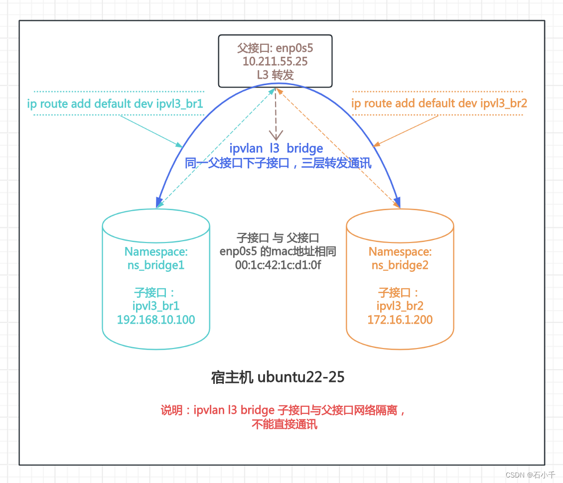
2.3.1.1 配置 IPVLAN l3 bridge 环境
- 创建父接口enp0s5的两个Ipvlan子接口:ipvl3_br1 和 ipvl3_br2
root@ubuntu22-25:~# ip link add link enp0s5 name ipvl3_br1 type ipvlan mode l3 bridge
root@ubuntu22-25:~# ip link add link enp0s5 name ipvl3_br2 type ipvlan mode l3 bridge
- 1
- 2
- 创建两个网络命名空间:ns_bridge1 和 ns_bridge2
root@ubuntu22-25:~# ip netns add ns_bridge1
root@ubuntu22-25:~# ip netns add ns_bridge2
- 1
- 2
- ipvl3_br1加入ns_bridge1,配置IP 192.168.10.100,并启用
root@ubuntu22-25:~# ip link set ipvl3_br1 netns ns_bridge1
root@ubuntu22-25:~# ip netns exec ns_bridge1 ip addr add 192.168.10.100/24 dev ipvl3_br1
root@ubuntu22-25:~# ip netns exec ns_bridge1 ip link set ipvl3_br1 up
root@ubuntu22-25:~# ip netns exec ns_bridge1 ip link set lo up
- 1
- 2
- 3
- 4
- ipvl3_br2加入ns_bridge2,配置IP 172.16.1.200,并启用
root@ubuntu22-25:~# ip link set ipvl3_br2 netns ns_bridge2
root@ubuntu22-25:~# ip netns exec ns_bridge2 ip addr add 172.16.1.200/24 dev ipvl3_br2
root@ubuntu22-25:~# ip netns exec ns_bridge2 ip link set ipvl3_br2 up
root@ubuntu22-25:~# ip netns exec ns_bridge2 ip link set lo up
- 1
- 2
- 3
- 4
- ns_bridge1 和 ns_bridge2 添加默认路由
root@ubuntu22-25:~# ip netns exec ns_bridge1 ip route add default dev ipvl3_br1
root@ubuntu22-25:~# ip netns exec ns_bridge2 ip route add default dev ipvl3_br2
// 查看ns_bridge2默认路由
root@ubuntu22-25:~# ip netns exec ns_bridge2 ip route
default dev ipvl3_br2 scope link
172.16.1.0/24 dev ipvl3_br2 proto kernel scope link src 172.16.1.200
- 1
- 2
- 3
- 4
- 5
- 6
2.3.1.2 测试 IPVLAN l3 bridge 子网卡通讯情况
- 测试ipvl3_br1 ping ipvl3_br2,通
root@ubuntu22-25:~# ip netns exec ns_bridge2 ping 192.168.10.100 -c3
PING 192.168.10.100 (192.168.10.100): 56 data bytes
64 bytes from 192.168.10.100: icmp_seq=0 ttl=64 time=0.063 ms
64 bytes from 192.168.10.100: icmp_seq=1 ttl=64 time=0.073 ms
64 bytes from 192.168.10.100: icmp_seq=2 ttl=64 time=0.072 ms
--- 192.168.10.100 ping statistics ---
3 packets transmitted, 3 packets received, 0% packet loss
round-trip min/avg/max/stddev = 0.063/0.069/0.073/0.000 ms
root@ubuntu22-25:~#
- 1
- 2
- 3
- 4
- 5
- 6
- 7
- 8
- 9
2.3.2 IPVLAN l3 private 同父接口下子接口通讯情况
1.测试步骤:以enp0s5为父接口,创建两个ipvlan子接口,mode:l3、flags:private(ipvl3_private1和ipvl3_private2),分别加入到网络命名空间ipvl3_private1和ipvl3_private2中。在命名空间中配置两个ipvlan子接口IP(ipvl3_private1 192.168.10.100,ipvl3_private2 172.16.1.200)并启用。测试两个ipvlan子接口网络通讯情况。
注意l3与l2不同的是,子接口需要配置路由。详见下图:
2.测试结果: IPVLAN l3 private模式下,同一父接口下的子接口禁止互相通讯
补充:“1.4.2 发包流程”中已经很清楚,只要是private,那么包就被drop。
2.3.2.1 配置 IPVLAN l3 private 环境
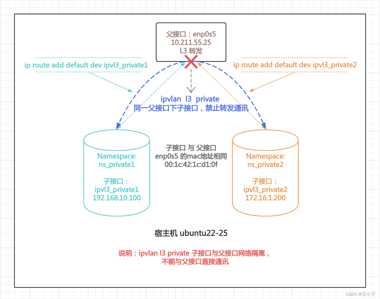
- 创建父接口enp0s5的两个Ipvlan子接口:ipvl3_private1 和 ipvl3_private2
root@ubuntu22-25:~# ip link add link enp0s5 name ipvl3_private1 type ipvlan mode l3 private
root@ubuntu22-25:~# ip link add link enp0s5 name ipvl3_private2 type ipvlan mode l3 private
- 1
- 2
- 创建两个网络命名空间:ns_private1 和 ns_private2
root@ubuntu22-25:~# ip netns add ns_private1
root@ubuntu22-25:~# ip netns add ns_private2
- 1
- 2
- ipvl3_private1加入ns_private1,配置IP 192.168.10.100,并启用
- ns_private1配置默认路由
root@ubuntu22-25:~# ip link set ipvl3_private1 netns ns_private1
root@ubuntu22-25:~# ip netns exec ns_private1 ip addr add 192.168.10.100/24 dev ipvl3_private1
root@ubuntu22-25:~# ip netns exec ns_private1 ip link set ipvl3_private1 up
root@ubuntu22-25:~# ip netns exec ns_private1 ip link set lo up
// 配置默认路由
root@ubuntu22-25:~# ip netns exec ns_private1 ip route add default dev ipvl3_private1
- 1
- 2
- 3
- 4
- 5
- 6
- ipvl3_private2加入ns_private2,配置IP 172.16.1.200,并启用
- ns_private2配置默认路由
root@ubuntu22-25:~# ip link set ipvl3_private2 netns ns_private2
root@ubuntu22-25:~# ip netns exec ns_private2 ip addr add 172.16.1.200/24 dev ipvl3_private2
root@ubuntu22-25:~# ip netns exec ns_private2 ip link set ipvl3_private2 up
root@ubuntu22-25:~# ip netns exec ns_private2 ip link set lo up
// 配置默认路由
root@ubuntu22-25:~# ip netns exec ns_private2 ip route add default dev ipvl3_private2
- 1
- 2
- 3
- 4
- 5
- 6
2.3.2.2 测试 IPVLAN l3 private 子网卡通讯情况
- l3 private模式下,子接口网络隔离,测试Ping,不通
// 查看ns_private2下ipvl3_private2的IP
root@ubuntu22-25:~# ip netns exec ns_private2 ip a
1: lo: <LOOPBACK,UP,LOWER_UP> mtu 65536 qdisc noqueue state UNKNOWN group default qlen 1000
    link/loopback 00:00:00:00:00:00 brd 00:00:00:00:00:00
    inet 127.0.0.1/8 scope host lo
       valid_lft forever preferred_lft forever
    inet6 ::1/128 scope host
       valid_lft forever preferred_lft forever
4: ipvl3_private2@if2: <BROADCAST,MULTICAST,NOARP,UP,LOWER_UP> mtu 1500 qdisc noqueue state UNKNOWN group default qlen 1000
    link/ether 00:1c:42:1c:d1:0f brd ff:ff:ff:ff:ff:ff link-netnsid 0
    inet 172.16.1.200/24 scope global ipvl3_private2
       valid_lft forever preferred_lft forever
    inet6 fe80::1c:4200:21c:d10f/64 scope link
       valid_lft forever preferred_lft forever

// 查看ns_private2下默认路由
root@ubuntu22-25:~# ip netns exec ns_private2 ip route
default dev ipvl3_private2 scope link
172.16.1.0/24 dev ipvl3_private2 proto kernel scope link src 172.16.1.200

// 测试子接口互相 Ping,不通
root@ubuntu22-25:~# ip netns exec ns_private2 ping 192.168.10.100 -c3
PING 192.168.10.100 (192.168.10.100): 56 data bytes
--- 192.168.10.100 ping statistics ---
3 packets transmitted, 0 packets received, 100% packet loss
- 1
- 2
- 3
- 4
- 5
- 6
- 7
- 8
- 9
- 10
- 11
- 12
- 13
- 14
- 15
- 16
- 17
- 18
- 19
- 20
- 21
- 22
- 23
- 24
- 25
2.3.3 IPVLAN l3 vepa 同父接口下子接口通讯情况
1.测试步骤:
- 使用宿主机ubuntu22-25 网卡enp0s5 创建两个ipvlan子接口,mode:l3、flags:vepa(ipvl3_vepa1和ipvl3_vepa2),分别加入到网络命名空间ns1和ns2中。在命名空间中配置两个ipvlan子接口IP(ipvl3_vepa1 192.168.10.100,ipvl3_vepa2 192.168.20.200)和默认路由。
- 在宿主机ubuntu22-25 添加静态路由,将两个ipvlan接口IP的外发路由指向宿主机ubuntu22-24(需要ubuntu22-24做外部路由,转发IP)
- 在宿主机ubuntu22-24 添加静态路由,将两个ipvlan接口IP的返回路由指向宿主机ubuntu22-25(ubuntu22-24完成转发后,需要返回数据包)
- 在宿主机ubuntu22-24 上开启路由转发功能,测试两个ipvlan子接口网络通讯的情况。
注意l3与l2不同的是,子接口需要配置路由。详见下图:
2.测试结果: IPVLAN l3 vepa模式下,父接口不转发子接口之间数据包,但外部路由支持时,相同父接口下的子接口可以通过外部路由转发通讯
补充:ipvlan l3 vepa 模式下,子接口数据包由父接口直接外发。详见上述 ”1.4.2 发包流程” 代码
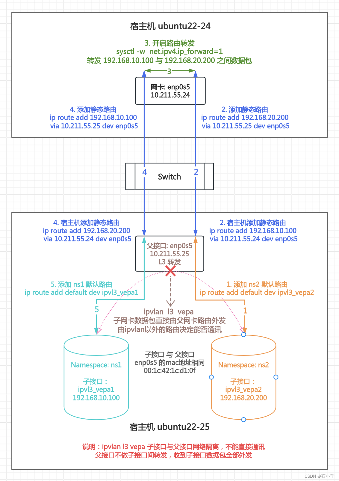
2.3.3.1 配置宿主机 ubuntu22-25
- 创建父接口enp0s5的两个Ipvlan子接口:ipvl3_vepa1 和 ipvl3_vepa2
root@ubuntu22-25:~# ip link add link enp0s5 name ipvl3_vepa1 type ipvlan mode l3 vepa
root@ubuntu22-25:~# ip link add link enp0s5 name ipvl3_vepa2 type ipvlan mode l3 vepa
- 1
- 2
- 创建两个网络命名空间:ns1 和 ns2
root@ubuntu22-25:~# ip netns add ns1
root@ubuntu22-25:~# ip netns add ns2
- 1
- 2
- ipvl3_vepa1加入ns1,配置IP 192.168.10.100,并启用
root@ubuntu22-25:~# ip link set ipvl3_vepa1 netns ns1
root@ubuntu22-25:~# ip netns exec ns1 ip addr add 192.168.10.100/24 dev ipvl3_vepa1
root@ubuntu22-25:~# ip netns exec ns1 ip link set lo up
root@ubuntu22-25:~# ip netns exec ns1 ip link set ipvl3_vepa1 up
root@ubuntu22-25:~# ip netns exec ns1 ip a
1: lo: <LOOPBACK,UP,LOWER_UP> mtu 65536 qdisc noqueue state UNKNOWN group default qlen 1000
    link/loopback 00:00:00:00:00:00 brd 00:00:00:00:00:00
    inet 127.0.0.1/8 scope host lo
       valid_lft forever preferred_lft forever
    inet6 ::1/128 scope host
       valid_lft forever preferred_lft forever
3: ipvl3_vepa1@if2: <BROADCAST,MULTICAST,NOARP,UP,LOWER_UP> mtu 1500 qdisc noqueue state UNKNOWN group default qlen 1000
    link/ether 00:1c:42:1c:d1:0f brd ff:ff:ff:ff:ff:ff link-netnsid 0
    inet 192.168.10.100/24 scope global ipvl3_vepa1
       valid_lft forever preferred_lft forever
    inet6 fe80::1c:4200:11c:d10f/64 scope link
       valid_lft forever preferred_lft forever
- 1
- 2
- 3
- 4
- 5
- 6
- 7
- 8
- 9
- 10
- 11
- 12
- 13
- 14
- 15
- 16
- 17
- ns1 使用 ipvl3_vepa1 配置默认路由
root@ubuntu22-25:~# ip netns exec ns1 ip route add default dev ipvl3_vepa1
root@ubuntu22-25:~# ip route
default via 10.211.55.1 dev enp0s5 proto static
10.211.55.0/24 dev enp0s5 proto kernel scope link src 10.211.55.25
root@ubuntu22-25:~# ip netns exec ns1 ip route
default dev ipvl3_vepa1 scope link
192.168.10.0/24 dev ipvl3_vepa1 proto kernel scope link src 192.168.10.100
- 1
- 2
- 3
- 4
- 5
- 6
- 7
- ipvl3_vepa2加入ns2,配置IP 192.168.2.200,并启用
root@ubuntu22-25:~# ip link set ipvl3_vepa2 netns ns2
root@ubuntu22-25:~# ip netns exec ns2 ip addr add 192.168.20.200/24 dev ipvl3_vepa2
root@ubuntu22-25:~# ip netns exec ns2 ip link set lo up
root@ubuntu22-25:~# ip netns exec ns2 ip link set ipvl3_vepa2 up
root@ubuntu22-25:~# ip netns exec ns2 ip a
1: lo: <LOOPBACK,UP,LOWER_UP> mtu 65536 qdisc noqueue state UNKNOWN group default qlen 1000
    link/loopback 00:00:00:00:00:00 brd 00:00:00:00:00:00
    inet 127.0.0.1/8 scope host lo
       valid_lft forever preferred_lft forever
    inet6 ::1/128 scope host
       valid_lft forever preferred_lft forever
4: ipvl3_vepa2@if2: <BROADCAST,MULTICAST,NOARP,UP,LOWER_UP> mtu 1500 qdisc noqueue state UNKNOWN group default qlen 1000
    link/ether 00:1c:42:1c:d1:0f brd ff:ff:ff:ff:ff:ff link-netnsid 0
    inet 192.168.20.200/24 scope global ipvl3_vepa2
       valid_lft forever preferred_lft forever
    inet6 fe80::1c:4200:21c:d10f/64 scope link
       valid_lft forever preferred_lft forever
- 1
- 2
- 3
- 4
- 5
- 6
- 7
- 8
- 9
- 10
- 11
- 12
- 13
- 14
- 15
- 16
- 17
- ns2 使用 ipvl3_vepa2 配置默认路由
root@ubuntu22-25:~# ip netns exec ns2 ip route add default dev ipvl3_vepa2
root@ubuntu22-25:~# ip netns exec ns2 ip route
default dev ipvl3_vepa2 scope link
192.168.20.0/24 dev ipvl3_vepa2 proto kernel scope link src 192.168.20.200
- 1
- 2
- 3
- 4
2.3.3.2 测试 IPVLAN l3 vepa 默认情况下子接口通讯情况
- 测试 IPVLAN 子接口间通信(ns2 Ping 192.168.10.100),不通
ipvlan l3 vepa 模式下,子接口数据包由父接口直接外发,父接口不做子接口之间转发。详见上述 ”1.4.2 发包流程” 代码
root@ubuntu22-25:~# ip netns exec ns2 ping 192.168.10.100 -c3
PING 192.168.10.100 (192.168.10.100): 56 data bytes
--- 192.168.10.100 ping statistics ---
3 packets transmitted, 0 packets received, 100% packet loss
- 1
- 2
- 3
- 4
- 测试 IPVLAN 子接口 Ping 父接口,不通
// 父网卡配合与ns1 和 ns2 同网段IP地址
root@ubuntu22-25:~# ip addr add 192.168.10.254/24 dev enp0s5
root@ubuntu22-25:~# ip addr add 192.168.20.254/24 dev enp0s5
// 父网卡与子网卡不能直接通讯
root@ubuntu22-25:~# ping 192.168.10.100 -c2
PING 192.168.10.100 (192.168.10.100): 56 data bytes
92 bytes from ubuntu22-25 (192.168.10.254): Destination Host Unreachable
92 bytes from ubuntu22-25 (192.168.10.254): Destination Host Unreachable
--- 192.168.10.100 ping statistics ---
2 packets transmitted, 0 packets received, 100% packet loss
root@ubuntu22-25:~# ping 192.168.20.200 -c2
PING 192.168.20.200 (192.168.20.200): 56 data bytes
92 bytes from ubuntu22-25 (192.168.20.254): Destination Host Unreachable
92 bytes from ubuntu22-25 (192.168.20.254): Destination Host Unreachable
--- 192.168.20.200 ping statistics ---
2 packets transmitted, 0 packets received, 100% packet loss
- 1
- 2
- 3
- 4
- 5
- 6
- 7
- 8
- 9
- 10
- 11
- 12
- 13
- 14
- 15
- 16
- 宿主机ubuntu22-25 配置静态路由
- 利用外部ubuntu22-24的路由测试 ipvlan l3 vepa 子接口间通讯,ubuntu22-25 将192.168.10.100 和 192.168.20.200 路由指向ubuntu22-24的IP 10.211.55.24。
root@ubuntu22-25:~# ip route add 192.168.10.100 via 10.211.55.24 dev enp0s5
root@ubuntu22-25:~# ip route add 192.168.20.200 via 10.211.55.24 dev enp0s5
root@ubuntu22-25:~# ip route
default via 10.211.55.1 dev enp0s5 proto static
10.211.55.0/24 dev enp0s5 proto kernel scope link src 10.211.55.25
192.168.10.100 via 10.211.55.24 dev enp0s5
192.168.20.200 via 10.211.55.24 dev enp0s5
- 1
- 2
- 3
- 4
- 5
- 6
- 7
2.3.3.3 配置宿主机 ubuntu22-24
- 宿主机ubuntu22-24 配置前情况
root@ubuntu22-24:~# ip a
1: lo: <LOOPBACK,UP,LOWER_UP> mtu 65536 qdisc noqueue state UNKNOWN group default qlen 1000
    link/loopback 00:00:00:00:00:00 brd 00:00:00:00:00:00
    inet 127.0.0.1/8 scope host lo
       valid_lft forever preferred_lft forever
    inet6 ::1/128 scope host
       valid_lft forever preferred_lft forever
2: enp0s5: <BROADCAST,MULTICAST,UP,LOWER_UP> mtu 1500 qdisc fq_codel state UP group default qlen 1000
    link/ether 00:1c:42:5e:4d:21 brd ff:ff:ff:ff:ff:ff
    inet 10.211.55.24/24 brd 10.211.55.255 scope global enp0s5
       valid_lft forever preferred_lft forever
    inet6 fdb2:2c26:f4e4:0:21c:42ff:fe5e:4d21/64 scope global dynamic mngtmpaddr noprefixroute
       valid_lft 2591931sec preferred_lft 604731sec
    inet6 fe80::21c:42ff:fe5e:4d21/64 scope link
       valid_lft forever preferred_lft forever
root@ubuntu22-24:~# ip route
default via 10.211.55.1 dev enp0s5 proto static
10.211.55.0/24 dev enp0s5 proto kernel scope link src 10.211.55.24
root@ubuntu22-24:~#
- 1
- 2
- 3
- 4
- 5
- 6
- 7
- 8
- 9
- 10
- 11
- 12
- 13
- 14
- 15
- 16
- 17
- 18
- 19
- 宿主机ubuntu22-24 配置静态路由
- ubuntu22-24 添加反向路由与ubuntu22-25配置的静态路由对应。将192.168.10.100 和 192.168.20.200 路由指回ubuntu22-25的IP 10.211.55.25。
root@ubuntu22-24:~# ip route add 192.168.10.100 via 10.211.55.25 dev enp0s5
root@ubuntu22-24:~# ip route add 192.168.20.200 via 10.211.55.25 dev enp0s5
root@ubuntu22-24:~# ip route
default via 10.211.55.1 dev enp0s5 proto static
10.211.55.0/24 dev enp0s5 proto kernel scope link src 10.211.55.24
192.168.10.100 via 10.211.55.25 dev enp0s5
192.168.20.200 via 10.211.55.25 dev enp0s5
- 1
- 2
- 3
- 4
- 5
- 6
- 7
2.3.3.4 测试 IPVLAN l3 vepa 经外部路由转发下子接口通讯情况
- 测试宿主机ubuntu22-24与ipvlan l3 vepa子网卡通讯
- ubuntu22-24 可以Ping 192.168.10.100 和 192.168.20.200 ,通。
- 说明ubuntu22-25 上的 ipvlan l3 vepa 子接口经过父接口三层转发、宿主机静态路由转发,可以与外部通讯。
ubuntu22-24 --> ubuntu22-24 静态路由 --> ubuntu22-25 ipvlan父接口 --> ipvlan子接口
root@ubuntu22-24:~# ping 192.168.10.100 -c3
PING 192.168.10.100 (192.168.10.100): 56 data bytes
64 bytes from 192.168.10.100: icmp_seq=0 ttl=64 time=0.688 ms
64 bytes from 192.168.10.100: icmp_seq=1 ttl=64 time=0.522 ms
^C--- 192.168.10.100 ping statistics ---
2 packets transmitted, 2 packets received, 0% packet loss
round-trip min/avg/max/stddev = 0.522/0.605/0.688/0.083 ms
root@ubuntu22-24:~# ping 192.168.20.200 -c3
PING 192.168.20.200 (192.168.20.200): 56 data bytes
64 bytes from 192.168.20.200: icmp_seq=0 ttl=64 time=0.431 ms
64 bytes from 192.168.20.200: icmp_seq=1 ttl=64 time=0.499 ms
^C--- 192.168.20.200 ping statistics ---
2 packets transmitted, 2 packets received, 0% packet loss
round-trip min/avg/max/stddev = 0.431/0.465/0.499/0.034 ms
- 1
- 2
- 3
- 4
- 5
- 6
- 7
- 8
- 9
- 10
- 11
- 12
- 13
- 14
- ubuntu22-24 开启 IP转发功能
root@ubuntu22-24:~# sysctl net.ipv4.ip_forward=1
net.ipv4.ip_forward = 1
- 1
- 2
- 测试ubuntu22-25 经过 ubuntu22-24 IP转发与ipvlan l3 vepa子接口通讯
- ubuntu22-25 可以Ping192.168.10.100 和 192.168.20.200 ,通 。
- 说明ubuntu22-25 经 ubuntu22-24 IP转发,再经 ipvlan l3 vepa 父接口三层转发,可以与ipvlan l3 vepa 子接口通讯。
ubuntu22-25 --> ubuntu22-25 静态路由 --> ubuntu22-24 IP转发 --> ubuntu22-24 静态路由 --> ubuntu22-25 ipvlan父接口 --> ipvlan子接口
// 查看 ubuntu22-25 的IP
root@ubuntu22-25:~# ip a show enp0s5
2: enp0s5: <BROADCAST,MULTICAST,UP,LOWER_UP> mtu 1500 qdisc fq_codel state UP group default qlen 1000
    link/ether 00:1c:42:1c:d1:0f brd ff:ff:ff:ff:ff:ff
    inet 10.211.55.25/24 brd 10.211.55.255 scope global enp0s5
       valid_lft forever preferred_lft forever
    inet 192.168.10.254/24 scope global enp0s5
       valid_lft forever preferred_lft forever
    inet 192.168.20.254/24 scope global enp0s5
       valid_lft forever preferred_lft forever
    inet6 fdb2:2c26:f4e4:0:21c:42ff:fe1c:d10f/64 scope global dynamic mngtmpaddr noprefixroute
       valid_lft 2591806sec preferred_lft 604606sec
    inet6 fe80::21c:42ff:fe1c:d10f/64 scope link
       valid_lft forever preferred_lft forever
// ubuntu22-25 Ping 192.168.20.200,通
root@ubuntu22-25:~# ping 192.168.20.200
PING 192.168.20.200 (192.168.20.200): 56 data bytes
92 bytes from 10.211.55.24: Redirect Host
64 bytes from 192.168.20.200: icmp_seq=0 ttl=64 time=91.659 ms
64 bytes from 192.168.20.200: icmp_seq=1 ttl=64 time=0.521 ms
64 bytes from 192.168.20.200: icmp_seq=2 ttl=64 time=0.519 ms
64 bytes from 192.168.20.200: icmp_seq=3 ttl=64 time=0.537 ms
64 bytes from 192.168.20.200: icmp_seq=4 ttl=64 time=0.535 ms
64 bytes from 192.168.20.200: icmp_seq=5 ttl=64 time=0.556 ms
^C92 bytes from 10.211.55.24: Redirect Host
--- 192.168.20.200 ping statistics ---
7 packets transmitted, 6 packets received, 14% packet loss
round-trip min/avg/max/stddev = 0.519/15.721/91.659/33.960 ms
// ubuntu22-25 Ping 192.168.10.100,通
root@ubuntu22-25:~# ping 192.168.10.100
PING 192.168.10.100 (192.168.10.100): 56 data bytes
64 bytes from 192.168.10.100: icmp_seq=0 ttl=64 time=0.436 ms
64 bytes from 192.168.10.100: icmp_seq=1 ttl=64 time=0.509 ms
64 bytes from 192.168.10.100: icmp_seq=2 ttl=64 time=0.603 ms
64 bytes from 192.168.10.100: icmp_seq=3 ttl=64 time=0.591 ms
^C--- 192.168.10.100 ping statistics ---
4 packets transmitted, 4 packets received, 0% packet loss
round-trip min/avg/max/stddev = 0.436/0.535/0.603/0.068 ms
- 1
- 2
- 3
- 4
- 5
- 6
- 7
- 8
- 9
- 10
- 11
- 12
- 13
- 14
- 15
- 16
- 17
- 18
- 19
- 20
- 21
- 22
- 23
- 24
- 25
- 26
- 27
- 28
- 29
- 30
- 31
- 32
- 33
- 34
- 35
- 36
- 37
- 38
- 测试ipvlan l3 vepa子接口间,经 ubuntu22-24 IP转发互相通讯
- ipvlan l3 vepa子接口: ipvl3_vepa1 (192.168.10.100) 可以Ping ipvlan l3 vepa子接口: ipvl3_vepa2 (192.168.20.200),通。
- 说明ipvlan l3 vepa 子接口之间,经过外部路由转发,可以互相通讯。
ipvl3_vepa1 --> ubuntu22-25 ipvlan父接口 --> ubuntu22-25 静态路由 --> ubuntu22-24 IP转发 --> ubuntu22-24 静态路由 --> ubuntu22-25 ipvlan父接口 --> ipvl3_vepa2
root@ubuntu22-25:~# ip netns exec ns1 ping 192.168.20.200
PING 192.168.20.200 (192.168.20.200): 56 data bytes
92 bytes from 10.211.55.24: Redirect Host
64 bytes from 192.168.20.200: icmp_seq=0 ttl=63 time=0.795 ms
64 bytes from 192.168.20.200: icmp_seq=1 ttl=63 time=0.761 ms
64 bytes from 192.168.20.200: icmp_seq=2 ttl=63 time=0.725 ms
64 bytes from 192.168.20.200: icmp_seq=3 ttl=63 time=0.730 ms
64 bytes from 192.168.20.200: icmp_seq=4 ttl=63 time=0.749 ms
64 bytes from 192.168.20.200: icmp_seq=5 ttl=63 time=0.770 ms
64 bytes from 192.168.20.200: icmp_seq=6 ttl=63 time=0.761 ms
^C--- 192.168.20.200 ping statistics ---
7 packets transmitted, 7 packets received, 0% packet loss
round-trip min/avg/max/stddev = 0.725/0.756/0.795/0.000 ms
- 1
- 2
- 3
- 4
- 5
- 6
- 7
- 8
- 9
- 10
- 11
- 12
- 13
2.3.4 IPVLAN l3 bridge子接口与父接口通讯情况
1.测试步骤:
- 在宿主机ubuntu22-25上,以enp0s5(10.211.55.25)作为父接口创建两个ipvlan子接口(iplv3_bridge1和iplv3_bridge2),mode:l3、flags:bridge。子接口iplv3_bridge1加入到网络命名空间ns1,配置IP(192.168.10.100)并启用;子接口iplv2_bridge2与父接口在相同网络命名空间中,配置与父接口同段IP(10.211.55.254)并启用
- 在宿主机ubuntu22-24上配置访问ipvlan子接口iplv3_bridge1的静态路由
- 测试子接口iplv2_bridge1与父接口enp0s5网络通讯情况,如下图:
2.测试结果:IPVLAN l3 bridge模式下,父接口与子接口网络隔离,不能直接通讯,但是子接口可以通过与父接口同网络命名空间下的其它子接口转发通讯
补充:vepa与private模式下,ipvlan子接口之间无法直接通讯,无法实现中转
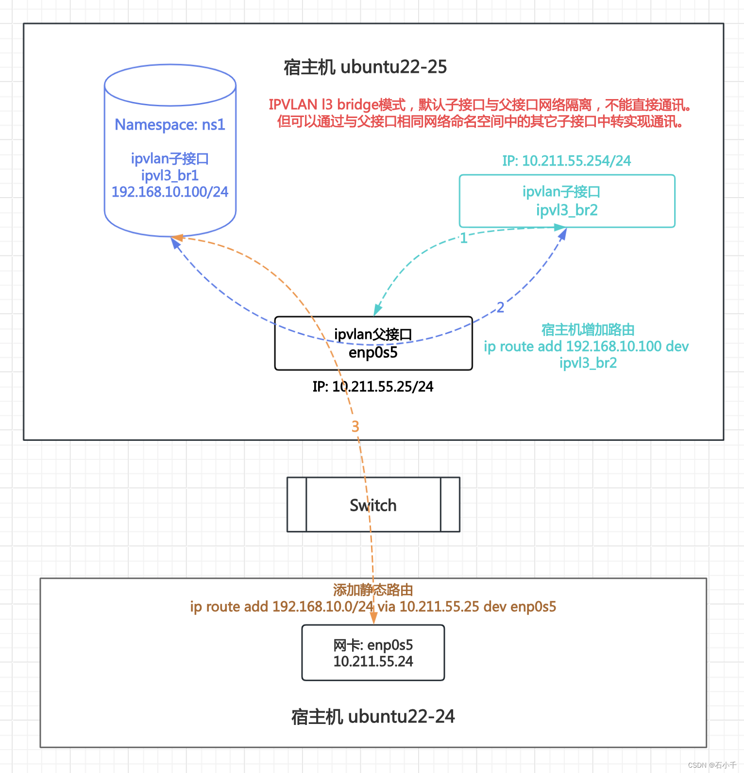
2.3.4.1 配置IPVLAN l3 bridge 子接口与父接口通讯环境
- 创建网络命名空间ns1
root@ubuntu22-25:~# ip netns add ns1
- 1
- 创建两个ipvlan子接口,mode l3,flags bridge:ipvl3_br1 和 ipvl3_br2
root@ubuntu22-25:~# ip link add link enp0s5 name ipvl3_br1 type ipvlan mode l3 bridge
root@ubuntu22-25:~# ip link add link enp0s5 name ipvl3_br2 type ipvlan mode l3 bridge
- 1
- 2
- 配置ipvan子接口ipvl3_br1
- ipvan子接口ipvl3_br1加入ns1
- ipvl3_br1配置IP 192.168.10.100/24
- ns1 使用 ipvl3_br1 配置默认路由
// ipvl3_br1 加入 ns1
root@ubuntu22-25:~# ip link set ipvl3_br1 netns ns1
// ipvl3_br1配置IP 192.168.10.100
root@ubuntu22-25:~# ip netns exec ns1 ip addr add 192.168.10.100/24 dev ipvl3_br1
root@ubuntu22-25:~# ip netns exec ns1 ip link set ipvl3_br1 up
root@ubuntu22-25:~# ip netns exec ns1 ip link set lo up
// 查看配置结果
root@ubuntu22-25:~# ip netns exec ns1 ip a
1: lo: <LOOPBACK,UP,LOWER_UP> mtu 65536 qdisc noqueue state UNKNOWN group default qlen 1000
    link/loopback 00:00:00:00:00:00 brd 00:00:00:00:00:00
    inet 127.0.0.1/8 scope host lo
       valid_lft forever preferred_lft forever
    inet6 ::1/128 scope host
       valid_lft forever preferred_lft forever
3: ipvl3_br1@if2: <BROADCAST,MULTICAST,NOARP,UP,LOWER_UP> mtu 1500 qdisc noqueue state UNKNOWN group default qlen 1000
    link/ether 00:1c:42:1c:d1:0f brd ff:ff:ff:ff:ff:ff link-netnsid 0
    inet 192.168.10.100/24 scope global ipvl3_br1
       valid_lft forever preferred_lft forever
    inet6 fe80::1c:4200:11c:d10f/64 scope link
       valid_lft forever preferred_lft forever
// 配置默认路由
root@ubuntu22-25:~# ip netns exec ns1 ip route add default dev ipvl3_br1
// 查看配置结果
root@ubuntu22-25:~# ip netns exec ns1 ip r
default dev ipvl3_br1 scope link
192.168.10.0/24 dev ipvl3_br1 proto kernel scope link src 192.168.10.100
root@ubuntu22-25:~#
- 1
- 2
- 3
- 4
- 5
- 6
- 7
- 8
- 9
- 10
- 11
- 12
- 13
- 14
- 15
- 16
- 17
- 18
- 19
- 20
- 21
- 22
- 23
- 24
- 25
- 26
- 27
- 配置ipvlan子接口ipvl3_br2
- ipvl3_br2配置IP 10.211.55.254/24(与父接口enp0s5 10.211.55.25 同段)
// ipvl3_br2 配置IP
root@ubuntu22-25:~# ip addr add 10.211.55.254/24 dev  ipvl3_br2
root@ubuntu22-25:~# ip link set ipvl3_br2 up
// 查看配置结果
root@ubuntu22-25:~# ip a
1: lo: <LOOPBACK,UP,LOWER_UP> mtu 65536 qdisc noqueue state UNKNOWN group default qlen 1000
    link/loopback 00:00:00:00:00:00 brd 00:00:00:00:00:00
    inet 127.0.0.1/8 scope host lo
       valid_lft forever preferred_lft forever
    inet6 ::1/128 scope host
       valid_lft forever preferred_lft forever
2: enp0s5: <BROADCAST,MULTICAST,UP,LOWER_UP> mtu 1500 qdisc fq_codel state UP group default qlen 1000
    link/ether 00:1c:42:1c:d1:0f brd ff:ff:ff:ff:ff:ff
    inet 10.211.55.25/24 brd 10.211.55.255 scope global enp0s5
       valid_lft forever preferred_lft forever
    inet6 fdb2:2c26:f4e4:0:21c:42ff:fe1c:d10f/64 scope global dynamic mngtmpaddr noprefixroute
       valid_lft 2591934sec preferred_lft 604734sec
    inet6 fe80::21c:42ff:fe1c:d10f/64 scope link
       valid_lft forever preferred_lft forever
4: ipvl3_br2@enp0s5: <BROADCAST,MULTICAST,NOARP,UP,LOWER_UP> mtu 1500 qdisc noqueue state UNKNOWN group default qlen 1000
    link/ether 00:1c:42:1c:d1:0f brd ff:ff:ff:ff:ff:ff
    inet 10.211.55.254/24 scope global ipvl3_br2
       valid_lft forever preferred_lft forever
    inet6 fe80::1c:4200:21c:d10f/64 scope link
       valid_lft forever preferred_lft forever
- 1
- 2
- 3
- 4
- 5
- 6
- 7
- 8
- 9
- 10
- 11
- 12
- 13
- 14
- 15
- 16
- 17
- 18
- 19
- 20
- 21
- 22
- 23
- 24
- 25
- 配置宿主机ubuntu22-24 访问ipvlan子接口ipvl3_br1的静态路由
为了配合测试ipvlan子接口ipvl3_br1 与外部通讯
// 配置宿主机ubuntu22-24 的静态路由
root@ubuntu22-24:~# ip route add 192.168.10.0/24 via 10.211.55.25 dev enp0s5
// 查看配置结果
root@ubuntu22-24:~# ip route
default via 10.211.55.1 dev enp0s5 proto static
10.211.55.0/24 dev enp0s5 proto kernel scope link src 10.211.55.24
192.168.10.0/24 via 10.211.55.25 dev enp0s5
root@ubuntu22-24:~#
- 1
- 2
- 3
- 4
- 5
- 6
- 7
- 8
2.3.4.2 测试IPVLAN l3 bridge 子接口与父接口通讯
- ns1中ipvlan子接口ipvl3_br1 Ping 10.211.55.24(ubuntu22-24),通
root@ubuntu22-25:~# ip netns exec ns1 ping 10.211.55.24 -c3
PING 10.211.55.24 (10.211.55.24): 56 data bytes
64 bytes from 10.211.55.24: icmp_seq=0 ttl=64 time=0.484 ms
64 bytes from 10.211.55.24: icmp_seq=1 ttl=64 time=0.558 ms
64 bytes from 10.211.55.24: icmp_seq=2 ttl=64 time=0.697 ms
--- 10.211.55.24 ping statistics ---
3 packets transmitted, 3 packets received, 0% packet loss
round-trip min/avg/max/stddev = 0.484/0.580/0.697/0.088 ms
root@ubuntu22-25:~#
- 1
- 2
- 3
- 4
- 5
- 6
- 7
- 8
- 9
- ns1中ipvlan子接口ipvl3_br1 Ping 10.211.55.25(ipvlan父接口),不通
root@ubuntu22-25:~# ip netns exec ns1 ping 10.211.55.25 -c3
PING 10.211.55.25 (10.211.55.25): 56 data bytes
--- 10.211.55.25 ping statistics ---
3 packets transmitted, 0 packets received, 100% packet loss
- 1
- 2
- 3
- 4
- 宿主机默认命名空间下配置访问192.168.10.100的静态路由
配置使用ipvlan子接口ipvl3_br2进行中转
root@ubuntu22-25:~# ip route add 192.168.10.100 dev ipvl3_br2
root@ubuntu22-25:~# ip route
default via 10.211.55.1 dev enp0s5 proto static
10.211.55.0/24 dev ipvl3_br2 proto kernel scope link src 10.211.55.254
10.211.55.0/24 dev enp0s5 proto kernel scope link src 10.211.55.25
192.168.10.100 dev ipvl3_br2 scope link
root@ubuntu22-25:~#
- 1
- 2
- 3
- 4
- 5
- 6
- 7
- ipvlan子接口ipvl3_br1经ipvl3_br2转发与父接口enp0s5直接通讯
- ns1下ipvl3_br1(192.168.10.100)Ping 父接口(10.211.55.25),通
root@ubuntu22-25:~# ip netns exec ns1 ping 10.211.55.25 -c3
PING 10.211.55.25 (10.211.55.25): 56 data bytes
64 bytes from 10.211.55.25: icmp_seq=0 ttl=64 time=0.056 ms
64 bytes from 10.211.55.25: icmp_seq=1 ttl=64 time=0.084 ms
64 bytes from 10.211.55.25: icmp_seq=2 ttl=64 time=0.153 ms
--- 10.211.55.25 ping statistics ---
3 packets transmitted, 3 packets received, 0% packet loss
round-trip min/avg/max/stddev = 0.056/0.098/0.153/0.041 ms
- 1
- 2
- 3
- 4
- 5
- 6
- 7
- 8
- ipvlan子接口ipvl3_br2上抓包,查看中转结果
- tcpdump -nn -e -i ipvl3_br2 not host 10.211.55.2
not host 抓包排除ssh客户端 10.211.55.2
-nn 两个n 表示不解析域名和端口
-e 在输出行打印出数据链路层的头部信息
-i 抓指定接口(网卡)的数据包
- tcpdump -nn -e -i ipvl3_br2 not host 10.211.55.2
root@ubuntu22-25:~# tcpdump -nn -e -i ipvl3_br2 not host 10.211.55.2
tcpdump: verbose output suppressed, use -v[v]... for full protocol decode
listening on ipvl3_br2, link-type EN10MB (Ethernet), snapshot length 262144 bytes
21:07:10.375827 00:1c:42:1c:d1:0f > 00:1c:42:1c:d1:0f, ethertype IPv4 (0x0800), length 98: 10.211.55.25 > 192.168.10.100: ICMP echo reply, id 1525, seq 0, length 64
21:07:11.377578 00:1c:42:1c:d1:0f > 00:1c:42:1c:d1:0f, ethertype IPv4 (0x0800), length 98: 10.211.55.25 > 192.168.10.100: ICMP echo reply, id 1525, seq 1, length 64
21:07:12.379822 00:1c:42:1c:d1:0f > 00:1c:42:1c:d1:0f, ethertype IPv4 (0x0800), length 98: 10.211.55.25 > 192.168.10.100: ICMP echo reply, id 1525, seq 2, length 64
^C
3 packets captured
3 packets received by filter
0 packets dropped by kernel
root@ubuntu22-25:~#
- 1
- 2
- 3
- 4
- 5
- 6
- 7
- 8
- 9
- 10
- 11
2.4 测试 IPVLAN L3S
IPVLAN L3S 与 IPVLAN L3 功能非常类似,本节内容不再重复测试,只介绍两者区别:IPVLAN L3S启用了iptables (conn-tracking)
2.4.1 IPVLAN l3s 使用IPtables状态过滤(conntrack)
1.测试步骤:
- 宿主机ubuntu22-25 启用nf_conntrack模块。
- 使用宿主机ubuntu22-25 网卡enp0s5 创建两个ipvlan子接口,mode:l3s、flags:bridge(l3s_bridge1和l3s_bridge2),分别加入到网络命名空间ns_bridge1和ns_bridge2中。在命名空间中配置两个ipvlan子接口IP(l3s_bridge1 192.168.10.100,l3s_bridge2 172.16.1.200)和默认路由。
- 在宿主机ubuntu22-24 添加静态路由,将访问ipvlan子接口IP的路由指向宿主机ubuntu22-25。
- 宿主机ubuntu22-25 配置iptables conntrack过滤规则。
- 测试ipvlan子接口网络通讯的iptables状态过滤情况。
注意l3s与l2不同的是,子接口需要配置路由。详见下图:
2.测试结果: IPVLAN l3s 模式下,可以通过iptables conntrack管控网络通讯
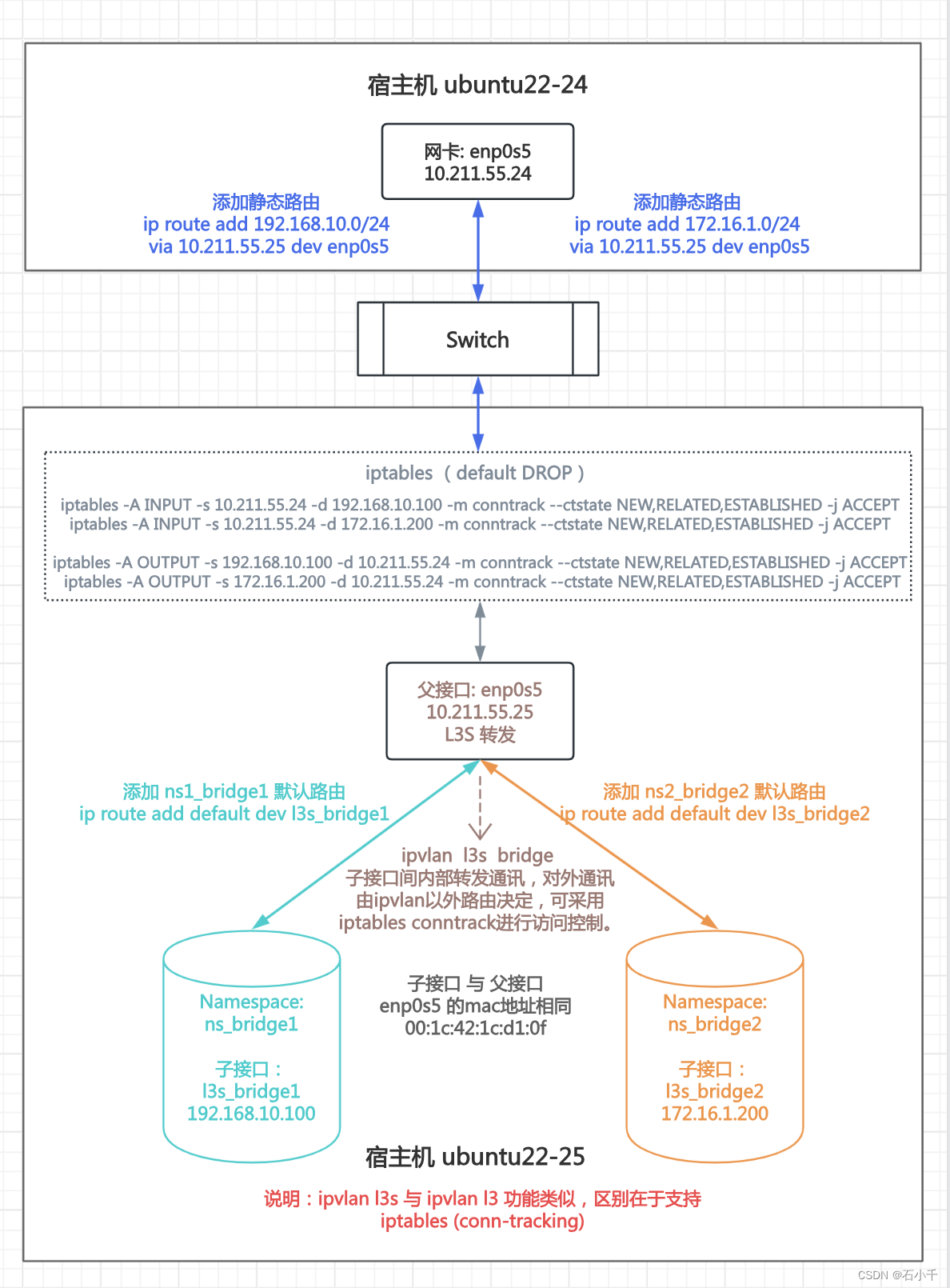
2.4.1.1 配置IPVLAN L3S测试环境
- 宿主机ubuntu22-25 启用nf_conntrack模块
// 加载nf_conntrack模块
root@ubuntu22-25:~# modprobe nf_conntrack
- 1
- 2
// 检查内核是否加载nf_conntrack模块
root@ubuntu22-25:~# lsmod | grep nf_conntrack
nf_conntrack_netlink    49152  0
nf_conntrack          172032  1 nf_conntrack_netlink
nf_defrag_ipv6         24576  1 nf_conntrack
nf_defrag_ipv4         16384  1 nf_conntrack
nfnetlink              20480  6 nf_conntrack_netlink
libcrc32c              16384  3 nf_conntrack,btrfs,raid456
- 1
- 2
- 3
- 4
- 5
- 6
- 7
- 8
// 查看状态跟踪记录。当前没有记录。
root@ubuntu22-25:~# conntrack -L -o extended
conntrack v1.4.6 (conntrack-tools): 0 flow entries have been shown.
- 1
- 2
- 3
- 宿主机ubuntu22-25 配置网络命名空间:ns_bridge1 和 ns_bridge2
- 宿主机ubuntu22-25 配置IPVLAN l3s子接口:l3s_bridge1 和 l3s_bridge2
// 创建两个网络命名空间:ns_bridge1 和 ns_bridge2
root@ubuntu22-25:~# ip netns add ns_bridge1
root@ubuntu22-25:~# ip netns add ns_bridge2
// 创建两个ipvlan子接口,mode l3s,flags bridge
root@ubuntu22-25:~# ip link add link enp0s5 name l3s_bridge1 type ipvlan mode l3s bridge
root@ubuntu22-25:~# ip link add link enp0s5 name l3s_bridge2 type ipvlan mode l3s bridge
- 1
- 2
- 3
- 4
- 5
- 6
- 将l3s_bridge1 加入ns_bridge1,配置IP 192.168.10.100
- 使用l3s_bridge1,配置ns_bridge1默认路由
// 将ipvlan子接口l3s_bridge1 加入网络命名空间ns_bridge1
root@ubuntu22-25:~# ip link set l3s_bridge1 netns ns_bridge1
// 配置IP 192.168.10.100 并启用
root@ubuntu22-25:~# ip netns exec ns_bridge1 ip addr add 192.168.10.100/24 dev l3s_bridge1
root@ubuntu22-25:~# ip netns exec ns_bridge1 ip link set l3s_bridge1 up
root@ubuntu22-25:~# ip netns exec ns_bridge1 ip link set lo up
// 配置ns_bridge1的默认路由
root@ubuntu22-25:~# ip netns exec ns_bridge1 ip route add default dev l3s_bridge1
- 1
- 2
- 3
- 4
- 5
- 6
- 7
- 8
- 将l3s_bridge2 加入ns_bridge2,配置IP 172.16.1.200
- 使用l3s_bridge2,配置ns_bridge2默认路由
// 将ipvlan子接口l3s_bridge2 加入网络命名空间ns_bridge2
root@ubuntu22-25:~# ip link set l3s_bridge2 netns ns_bridge2
// 配置IP 172.16.1.200 并启用
root@ubuntu22-25:~# ip netns exec ns_bridge2 ip addr add 172.16.1.200/24 dev l3s_bridge2
root@ubuntu22-25:~# ip netns exec ns_bridge2 ip link set l3s_bridge2 up
root@ubuntu22-25:~# ip netns exec ns_bridge2 ip link set lo up
// 配置ns_bridge2的默认路由
root@ubuntu22-25:~# ip netns exec ns_bridge2 ip route add default dev l3s_bridge2
- 1
- 2
- 3
- 4
- 5
- 6
- 7
- 8
- 配置宿主机ubuntu22-24 静态路由,与ipvlan子接口通讯
// 添加访问ipvlan子接口IP的静态路由
root@ubuntu22-24:~# ip route add 192.168.10.0/24 via 10.211.55.25 dev enp0s5
root@ubuntu22-24:~# ip route add 172.16.1.0/24 via 10.211.55.25 dev enp0s5
// 查看添加结果
root@ubuntu22-24:~# ip route
default via 10.211.55.1 dev enp0s5 proto static
10.211.55.0/24 dev enp0s5 proto kernel scope link src 10.211.55.24
172.16.1.0/24 via 10.211.55.25 dev enp0s5
192.168.10.0/24 via 10.211.55.25 dev enp0s5
root@ubuntu22-24:~#
- 1
- 2
- 3
- 4
- 5
- 6
- 7
- 8
- 9
- 10
2.4.1.2 测试IPVLAN L3S 默认情况下网络通讯情况
- 查看ns_bridge1中 l3s_bridge1 的配置
root@ubuntu22-25:~# ip netns exec ns_bridge1 ip a show l3s_bridge1
3: l3s_bridge1@if2: <BROADCAST,MULTICAST,NOARP,UP,LOWER_UP> mtu 1500 qdisc noqueue state UP group default qlen 1000
    link/ether 00:1c:42:1c:d1:0f brd ff:ff:ff:ff:ff:ff link-netnsid 0
    inet 192.168.10.100/24 scope global l3s_bridge1
       valid_lft forever preferred_lft forever
    inet6 fe80::1c:4200:11c:d10f/64 scope link
       valid_lft forever preferred_lft forever
- 1
- 2
- 3
- 4
- 5
- 6
- 7
- 两个IPVLAN子接口间测试Ping
- ns_bridge1中 l3s_bridge1(192.168.10.100) Ping ns_bridge2中 l3s_bridge2(172.16.1.200),通
注意,当前模式是bridge,子接口之间内部转发通讯。private和vepa模式请参考 “2.3 测试IPVLAN L3”
- ns_bridge1中 l3s_bridge1(192.168.10.100) Ping ns_bridge2中 l3s_bridge2(172.16.1.200),通
root@ubuntu22-25:~# ip netns exec ns_bridge1 ping 172.16.1.200
PING 172.16.1.200 (172.16.1.200): 56 data bytes
64 bytes from 172.16.1.200: icmp_seq=0 ttl=64 time=0.063 ms
64 bytes from 172.16.1.200: icmp_seq=1 ttl=64 time=0.074 ms
64 bytes from 172.16.1.200: icmp_seq=2 ttl=64 time=0.073 ms
^C--- 172.16.1.200 ping statistics ---
3 packets transmitted, 3 packets received, 0% packet loss
round-trip min/avg/max/stddev = 0.063/0.084/0.146/0.028 ms
- 1
- 2
- 3
- 4
- 5
- 6
- 7
- 8
- 命名空间中IPVLAN子接口Ping 外部宿主机ubuntu22-24 IP ,通
- ns_bridge1中l3s_bridge1 IP 192.168.10.100
- 宿主机ubuntu22-24 IP 10.211.55.24
// 命名空间ns_bridge1中IPVLAN子接口 l3s_bridge1 IP 192.168.10.100
// Ping 宿主机ubuntu22-24 IP 10.211.55.24,通
root@ubuntu22-25:~# ip netns exec ns_bridge1 ping 10.211.55.24 -c3
PING 10.211.55.24 (10.211.55.24): 56 data bytes
64 bytes from 10.211.55.24: icmp_seq=0 ttl=64 time=0.424 ms
64 bytes from 10.211.55.24: icmp_seq=1 ttl=64 time=0.584 ms
64 bytes from 10.211.55.24: icmp_seq=2 ttl=64 time=0.403 ms
--- 10.211.55.24 ping statistics ---
3 packets transmitted, 3 packets received, 0% packet loss
round-trip min/avg/max/stddev = 0.403/0.470/0.584/0.081 ms
- 1
- 2
- 3
- 4
- 5
- 6
- 7
- 8
- 9
- 10
- 外部宿主机ubuntu22-24 Ping IPVLAN子接口 ,通
// 宿主机ubuntu22-24 Ping IPVLAN子接口l3s_bridge2的IP 172.16.1.200,通
root@ubuntu22-24:~# ping 172.16.1.200 -c3
PING 172.16.1.200 (172.16.1.200): 56 data bytes
64 bytes from 172.16.1.200: icmp_seq=0 ttl=64 time=0.449 ms
64 bytes from 172.16.1.200: icmp_seq=1 ttl=64 time=0.547 ms
64 bytes from 172.16.1.200: icmp_seq=2 ttl=64 time=0.309 ms
--- 172.16.1.200 ping statistics ---
3 packets transmitted, 3 packets received, 0% packet loss
round-trip min/avg/max/stddev = 0.309/0.435/0.547/0.098 ms
- 1
- 2
- 3
- 4
- 5
- 6
- 7
- 8
- 9
2.4.1.3 配置iptables 状态过滤规则
- 添加iptables filter表允许连接规则
- 确保ssh和已建立的连接不断开
// 允许外部连接22端口
root@ubuntu22-25:~# iptables -A INPUT -p tcp --dport 22 -j ACCEPT
// 允许保持已建立的连接
root@ubuntu22-25:~# iptables -A INPUT -m conntrack --ctstate RELATED,ESTABLISHED -j ACCEPT
// 允许保持已建立的连接
root@ubuntu22-25:~# iptables -A OUTPUT -m conntrack --ctstate RELATED,ESTABLISHED -j ACCEPT
- 1
- 2
- 3
- 4
- 5
- 6
- 修改iptables filter默认规则为DROP
// iptables filter表 INPUT 默认 DROP
root@ubuntu22-25:~# iptables -P INPUT DROP
// iptables filter表 INPUT 默认 DROP
root@ubuntu22-25:~# OUTPUT -P OUTPUT DROP
// iptables filter表 FORWARD 默认 DROP
root@ubuntu22-25:~# iptables -P FORWARD DROP
- 1
- 2
- 3
- 4
- 5
- 6
- 添加iptables filter 涉及ipvlan 连接状态的规则
- 添加外部宿主机ubuntu22-24 访问ipvlan子接口 的连接状态规则(INPUT链,ACCEPT)
- 添加ipvlan子接口 访问外部宿主机ubuntu22-24 的连接状态规则(OUTPUT链,ACCEPT)
说明:为了便于理解,针对每种连接都创建了一个独立规则,实际使用中可以合并简化。关于连接状态的概念请参见:Iptables状态跟踪机制介绍和优化探讨
// 添加宿主机ubuntu22-24 10.211.55.24 访问ipvlan子接口 192.168.10.100,ACCEPT
root@ubuntu22-25:~# iptables -A INPUT -s 10.211.55.24 -d 192.168.10.100 -m conntrack --ctstate NEW,RELATED,ESTABLISHED -j ACCEPT
// 添加宿主机ubuntu22-24 10.211.55.24 访问ipvlan子接口 172.16.1.200,ACCEPT
root@ubuntu22-25:~# iptables -A INPUT -s 10.211.55.24 -d 172.16.1.200 -m conntrack --ctstate NEW,RELATED,ESTABLISHED -j ACCEPT
// 添加ipvlan子接口 192.168.10.100 访问宿主机ubuntu22-24 10.211.55.24,ACCEPT
root@ubuntu22-25:~# iptables -A OUTPUT -s 192.168.10.100 -d 10.211.55.24 -m conntrack --ctstate NEW,RELATED,ESTABLISHED -j ACCEPT
// 添加ipvlan子接口 172.16.1.200 访问宿主机ubuntu22-24 10.211.55.24,ACCEPT
root@ubuntu22-25:~# iptables -A OUTPUT -s 172.16.1.200 -d 10.211.55.24 -m conntrack --ctstate NEW,RELATED,ESTABLISHED -j ACCEPT
- 1
- 2
- 3
- 4
- 5
- 6
- 7
- 8
- 查看iptables filter 表添加后过滤规则
root@ubuntu22-25:~# iptables -L -nv --line-number
// INPUT 链,默认DROP
Chain INPUT (policy DROP 87 packets, 6498 bytes)
num   pkts bytes target     prot opt in     out     source               destination
1        1    64 ACCEPT     tcp  --  *      *       0.0.0.0/0            0.0.0.0/0            tcp dpt:22
2     9230 6973K ACCEPT     all  --  *      *       0.0.0.0/0            0.0.0.0/0            ctstate RELATED,ESTABLISHED
3        2   168 ACCEPT     all  --  *      *       10.211.55.24         192.168.10.100       ctstate NEW,RELATED,ESTABLISHED
4        2   168 ACCEPT     all  --  *      *       10.211.55.24         172.16.1.200         ctstate NEW,RELATED,ESTABLISHED

// FORWARD 链,默认DROP
Chain FORWARD (policy DROP 0 packets, 0 bytes)
num   pkts bytes target     prot opt in     out     source               destination

// OUTPUT 链,默认DROP
Chain OUTPUT (policy DROP 470 packets, 33928 bytes)
num   pkts bytes target     prot opt in     out     source               destination
1     1242  290K ACCEPT     all  --  *      *       0.0.0.0/0            0.0.0.0/0            ctstate RELATED,ESTABLISHED
2        4   336 ACCEPT     all  --  *      *       192.168.10.100       10.211.55.24         ctstate NEW,RELATED,ESTABLISHED
3        0     0 ACCEPT     all  --  *      *       172.16.1.200         10.211.55.24         ctstate NEW,RELATED,ESTABLISHED
root@ubuntu22-25:~#
- 1
- 2
- 3
- 4
- 5
- 6
- 7
- 8
- 9
- 10
- 11
- 12
- 13
- 14
- 15
- 16
- 17
- 18
- 19
- 20
2.4.1.4 测试IPVLAN L3S的iptables 连接状态过滤
- 测试外部宿主机ubuntu22-24 Ping ipvlan子接口
- 宿主机ubuntu22-24 Ping 192.168.10.100(ipvlan子接口 l3s_bridge1)
- 宿主机ubuntu22-25 nf_conntrack创建对应连接记录10.211.55.24 --> 192.168.10.100
- iptables filter表依据INPUT链conntrack规则放行10.211.55.24 --> 192.168.10.100
- 宿主机ubuntu22-24 Ping 192.168.10.100,通
// 宿主机ubuntu22-24 Ping 192.168.10.100, iptables INPUT链规则放行,通
root@ubuntu22-24:~# ping 192.168.10.100 -c2
PING 192.168.10.100 (192.168.10.100): 56 data bytes
64 bytes from 192.168.10.100: icmp_seq=0 ttl=64 time=0.710 ms
64 bytes from 192.168.10.100: icmp_seq=1 ttl=64 time=0.350 ms
--- 192.168.10.100 ping statistics ---
2 packets transmitted, 2 packets received, 0% packet loss
round-trip min/avg/max/stddev = 0.350/0.530/0.710/0.180 ms
- 1
- 2
- 3
- 4
- 5
- 6
- 7
- 8
// 宿主机ubuntu22-25上对应产生的10.211.55.24 --> 192.168.10.100 的conntrack记录
root@ubuntu22-25:~# conntrack -L -o extended
ipv4     2 icmp     1 17 src=10.211.55.24 dst=192.168.10.100 type=8 code=0 id=4832 src=192.168.10.100 dst=10.211.55.24 type=0 code=0 id=4832 mark=0 use=1
ipv4     2 tcp      6 431999 ESTABLISHED src=10.211.55.2 dst=10.211.55.25 sport=65462 dport=22 src=10.211.55.25 dst=10.211.55.2 sport=22 dport=65462 [ASSURED] mark=0 use=1
conntrack v1.4.6 (conntrack-tools): 2 flow entries have been shown.
- 1
- 2
- 3
- 4
- 5
- 测试Ipvlan子接口l3s_bridge2 Ping 外部宿主机ubuntu22-24
- ipvlan子接口l3s_bridge2 Ping 10.211.55.24(宿主机ubuntu22-24)
- 宿主机ubuntu22-25 nf_conntrack创建对应连接记录172.16.1.200 --> 10.211.55.24
- iptables filter表依据OUTPUT链conntrack规则放行172.16.1.200 --> 10.211.55.24
- ipvlan子接口l3s_bridge2 Ping 10.211.55.24,通
// 宿主机ubuntu22-25 清空nf_conntrack 记录表
root@ubuntu22-25:~# conntrack -F
conntrack v1.4.6 (conntrack-tools): connection tracking table has been emptied.
- 1
- 2
- 3
// 查看ns_bridge2中l3s_bridge2的配置
root@ubuntu22-25:~# ip netns exec ns_bridge2 ip a show l3s_bridge2
4: l3s_bridge2@if2: <BROADCAST,MULTICAST,NOARP,UP,LOWER_UP> mtu 1500 qdisc noqueue state UP group default qlen 1000
    link/ether 00:1c:42:1c:d1:0f brd ff:ff:ff:ff:ff:ff link-netnsid 0
    inet 172.16.1.200/24 scope global l3s_bridge2
       valid_lft forever preferred_lft forever
    inet6 fe80::1c:4200:21c:d10f/64 scope link
       valid_lft forever preferred_lft forever
// ns_bridge2中l3s_bridge2 ping 10.211.55.24,iptables OUTPUT链规则放行,通
root@ubuntu22-25:~# ip netns exec ns_bridge2 ping 10.211.55.24 -c2
PING 10.211.55.24 (10.211.55.24): 56 data bytes
64 bytes from 10.211.55.24: icmp_seq=0 ttl=64 time=0.403 ms
64 bytes from 10.211.55.24: icmp_seq=1 ttl=64 time=0.586 ms
--- 10.211.55.24 ping statistics ---
2 packets transmitted, 2 packets received, 0% packet loss
round-trip min/avg/max/stddev = 0.403/0.494/0.586/0.092 ms
- 1
- 2
- 3
- 4
- 5
- 6
- 7
- 8
- 9
- 10
- 11
- 12
- 13
- 14
- 15
- 16
// 宿主机ubuntu22-25上对应产生的172.16.1.200 --> 10.211.55.24 的conntrack记录
root@ubuntu22-25:~# conntrack -L -o extended
ipv4     2 tcp      6 431999 ESTABLISHED src=10.211.55.2 dst=10.211.55.25 sport=65462 dport=22 src=10.211.55.25 dst=10.211.55.2 sport=22 dport=65462 [ASSURED] mark=0 use=1
ipv4     2 icmp     1 22 src=172.16.1.200 dst=10.211.55.24 type=8 code=0 id=2744 src=10.211.55.24 dst=172.16.1.200 type=0 code=0 id=2744 mark=0 use=1
conntrack v1.4.6 (conntrack-tools): 2 flow entries have been shown.
- 1
- 2
- 3
- 4
- 5
- iptables删除conntrack过滤放行规则后,对比测试
- 删除外部宿主机ubuntu22-24 访问ipvlan子接口的连接状态规则(INPUT链和OUTPUT链)
- 测试外部宿主机ubuntu22-24 Ping 192.168.10.100,iptables INPUT链规则默认丢弃,不通
- 测试ipvlan子接口l3s_bridge2 Ping 10.211.55.24,iptables OUTPUT链规则默认丢弃,不通
- ipvlan子接口之间正常访问,不在iptables 过滤范围,不受限制。
// 删除后的iptables filter,已经去除了与10.211.55.24相关的放行规则,默认是DROP
root@ubuntu22-25:~# iptables -L -nv --line-number
Chain INPUT (policy DROP 87 packets, 6498 bytes)
num   pkts bytes target     prot opt in     out     source               destination
1    10111 7057K ACCEPT     all  --  *      *       0.0.0.0/0            0.0.0.0/0            ctstate RELATED,ESTABLISHED
2        0     0 ACCEPT     tcp  --  *      *       0.0.0.0/0            0.0.0.0/0            tcp dpt:22

Chain FORWARD (policy DROP 0 packets, 0 bytes)
num   pkts bytes target     prot opt in     out     source               destination

Chain OUTPUT (policy DROP 575 packets, 45228 bytes)
num   pkts bytes target     prot opt in     out     source               destination
1     1731  372K ACCEPT     all  --  *      *       0.0.0.0/0            0.0.0.0/0            ctstate RELATED,ESTABLISHED
- 1
- 2
- 3
- 4
- 5
- 6
- 7
- 8
- 9
- 10
- 11
- 12
- 13
// 宿主机ubuntu22-24 Ping 192.168.10.100,iptables INPUT链规则丢弃,不通
root@ubuntu22-24:~# ping 192.168.10.100 -c3
PING 192.168.10.100 (192.168.10.100): 56 data bytes
--- 192.168.10.100 ping statistics ---
3 packets transmitted, 0 packets received, 100% packet loss
root@ubuntu22-24:~#
- 1
- 2
- 3
- 4
- 5
- 6
// 测试ipvlan子接口l3s_bridge2 Ping 10.211.55.24,iptables OUTPUT链规则丢弃,不通
root@ubuntu22-25:~# ip netns exec ns_bridge2 ping 10.211.55.24 -c3
PING 10.211.55.24 (10.211.55.24): 56 data bytes
--- 10.211.55.24 ping statistics ---
3 packets transmitted, 0 packets received, 100% packet loss
root@ubuntu22-25:~#
- 1
- 2
- 3
- 4
- 5
- 6
- ipvlan子接口之间正常访问,不在iptables(默认DROP) 过滤范围,不受限制
// 注意 ipvlan子接口之间正常访问,不在iptables 过滤范围,不受限制
root@ubuntu22-25:~# ip netns exec ns_bridge2 ping 192.168.10.100 -c2
PING 192.168.10.100 (192.168.10.100): 56 data bytes
64 bytes from 192.168.10.100: icmp_seq=0 ttl=64 time=0.096 ms
64 bytes from 192.168.10.100: icmp_seq=1 ttl=64 time=0.081 ms
--- 192.168.10.100 ping statistics ---
2 packets transmitted, 2 packets received, 0% packet loss
round-trip min/avg/max/stddev = 0.081/0.088/0.096/0.000 ms
- 1
- 2
- 3
- 4
- 5
- 6
- 7
- 8
3. 总结
-
Linux的ipvlan分l2层、l3和l3s三种mode,bridge、private、vepa三种flags,在同一父接口上均不可混用。其中l2是2层,l3和l3s是3层,区别是l3s支持iptables conntrack;bridge、private、vepa决定同父接口下子接口之间的通讯,bridge允许直接通讯、private禁止通讯、vepa可以通过外部转发通讯。
-
ipvlan子接口均可以与外部网络通讯,需要外部网络、路由支持;bridge下的ipvlan子接口可以通过与父接口同命名空间下的其它子接口中转,实现与父接口通讯。


