- 1H12-821题库详解_哪一参数不会影响master设备和backup设备认证协商结果
- 2抖音矩阵系统源码:开发搭建与技术详解_矩阵源码
- 3数据库大作业——基于qt开发的图书管理系统 (一)环境的配置与项目需求的分析
- 4解决github提交代码Support for password authentication was removed 问题_github克隆报错remote: support for password authenticat
- 5ZooKeeper详解
- 6Android开发—基于OpenCV实现相机实时图像识别跟踪,入职3个月的Android程序员面临转正_opencv实时图像追踪
- 7论数据湖与数据仓库一体化设计的必要性
- 8内控个人简历参考「精选篇」
- 9java代码实现Ceph连接_java ceph
- 10首页最新 多IP浏览器防关联:如何配置多个独立且稳定的IP地址?
eNSP——vpn技术-gre与mgre_ensp路由器gre
赞
踩
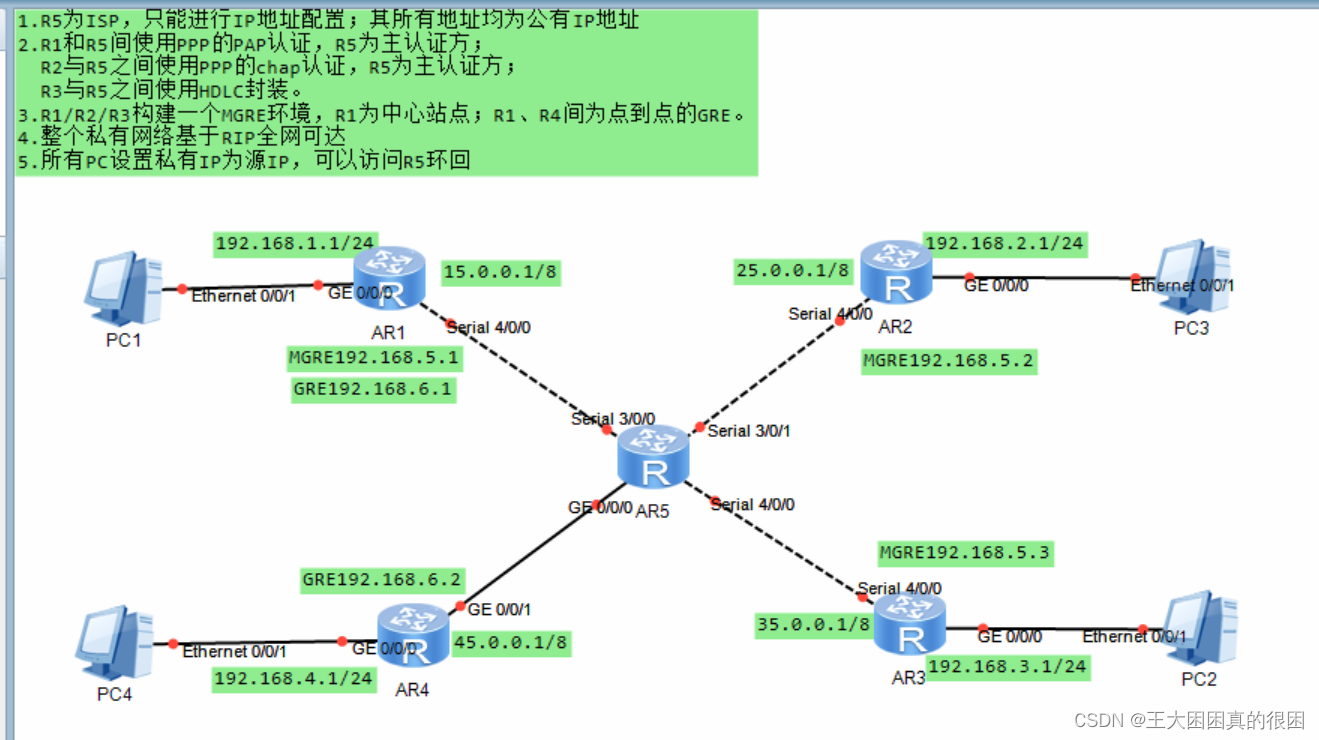
分析
如图,IP地址全部给好,我们只需要按着要求进行配置命令即好
1、R5作为ISP,即公网区域,公网区域包括了R5,R5的回环接口、R1的s4/0/0接口、R2的s4/0/0接口、R3的s4/0/0接口,与R4的g0/0/1接口。R1R2R3R4后连着私网。对ISP仅进行IP地址的配置,主机PC我选择手动配置。
2、点到点网络认证的配置,hdlc的封装与ppp协议的pap认证、chap认证,用户名密码随机。
3、今天的主要学习内容GRE与MGRE,用vpn虚拟专用网技术,建立隧道,实行封装,虚拟链路连通总部与分支,分支与分支,跨域公网(但实际还是要经过公网的转发),实现虚拟链路上点到点、点到多点(实际上也是gre封装)的数据传送。
4、rip协议宣告网段,形成完整的路由表,实现全网可达.就是要注意rip带来的问题:一是gre是点到点网络封装技术,即单播,而rip机制为多播(不可改变),单播导致分支上收不到中心想要传递的信息,因为中心只能发给一个分支,解决这个矛盾的方法就是改变环境,手工开启环境的多播模式;二是rip协议具有水平分割毒性逆转的防环技术,为避免环路设置,“从此口金不从此口出规则导致,仅仅依靠tunnel链路的数据包传送只能单向,分支路由表的信息不全,是rip机制问题,所以我们只能关掉rip的水平分割机制,所以对于这个问题,我们也要从最开始的规划中尽量避免环路。
5、私网可以访问公网网址,做缺省路由和nat协议,使PC可以访问R5回环
配置思路
一、路由器IP,主机IP及回环配置
二、hdlc与ppp的封装与认证
三、实现物理链路私网公网可达,私网可访问公网,但私网之间要看后面
四、建立隧道,实现r1r2r3的mgre封装
五、建立隧道,实现r1r4之间的gre封装
六、rip宣告,在mgre上,解决两个问题
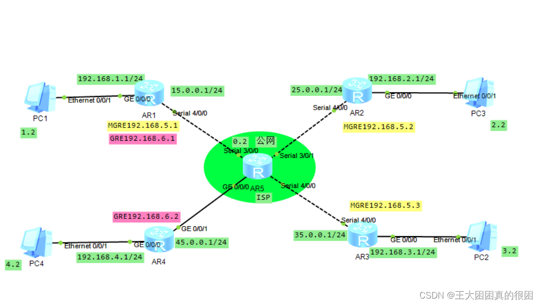
配置过程:
一、路由器
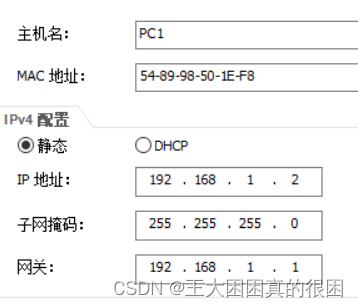
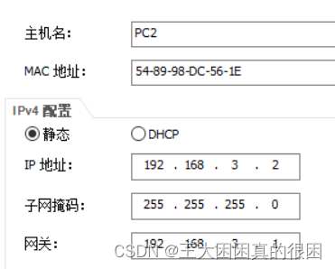
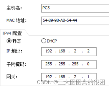
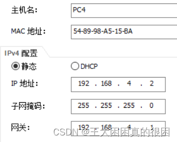
- [R1]int g0/0/0
- [R1-GigabitEthernet0/0/0]ip add 192.168.1.1 24
- Jan 25 2024 12:04:24-08:00 R1 %%01IFNET/4/LINK_STATE(l)[0]:The line protocol IP
- on the interface GigabitEthernet0/0/0 has entered the UP state.
- [R1-GigabitEthernet0/0/0]q
-
- [R1]int s4/0/0
- [R1-Serial4/0/0]ip add 15.0.0.1 24
- [R1-Serial4/0/0]q
-
- [R2]int g0/0/0
- [R2-GigabitEthernet0/0/0]ip add 192.168.2.1 24
- Jan 25 2024 12:07:03-08:00 R2 %%01IFNET/4/LINK_STATE(l)[0]:The line protocol IP
- on the interface GigabitEthernet0/0/0 has entered the UP state.
- [R2-GigabitEthernet0/0/0]q
- [R2]
- [R2]int s4/0/0
- [R2-Serial4/0/0]ip add 25.0.0.1 24
- [R2-Serial4/0/0]q
-
- [R3]int g0/0/0
- [R3-GigabitEthernet0/0/0]ip add 192.168.3.1 24
- Jan 25 2024 12:08:24-08:00 R3 %%01IFNET/4/LINK_STATE(l)[0]:The line protocol IP
- on the interface GigabitEthernet0/0/0 has entered the UP state.
- [R3-GigabitEthernet0/0/0]q
- [R3]
- [R3]int s4/0/0
- [R3-Serial4/0/0]ip add 35.0.0.1 24
- [R3-Serial4/0/0]q
- [R4]int g0/0/0
- [R4-GigabitEthernet0/0/0]ip add 192.168.4.1 24
- Jan 25 2024 12:10:17-08:00 R4 %%01IFNET/4/LINK_STATE(l)[0]:The line protocol IP
- on the interface GigabitEthernet0/0/0 has entered the UP state.
- [R4-GigabitEthernet0/0/0]q
- [R4]
- [R4]int g0/0/1
- [R4-GigabitEthernet0/0/1]ip add 45.0.0.1 24
- Jan 25 2024 12:10:36-08:00 R4 %%01IFNET/4/LINK_STATE(l)[1]:The line protocol IP
- on the interface GigabitEthernet0/0/1 has entered the UP state.
- [R4-GigabitEthernet0/0/1]q
- [ISP]int g0/0/0
- [ISP-GigabitEthernet0/0/0]ip add 45.0.0.2 24
- Jan 25 2024 12:12:25-08:00 ISP %%01IFNET/4/LINK_STATE(l)[0]:The line protocol IP
- on the interface GigabitEthernet0/0/0 has entered the UP state.
- [ISP-GigabitEthernet0/0/0]q
- [ISP]int s3/0/0
- [ISP-Serial3/0/0]ip add 15.0.0.2 24
- [ISP-Serial3/0/0]
- Jan 25 2024 12:12:50-08:00 ISP %%01IFNET/4/LINK_STATE(l)[1]:The line protocol PP
- P IPCP on the interface Serial3/0/0 has entered the UP state.
- [ISP-Serial3/0/0]q
- [ISP]int s3/0/1
- [ISP-Serial3/0/1]ip add 25.0.0.2 24
- [ISP-Serial3/0/1]
- Jan 25 2024 12:13:22-08:00 ISP %%01IFNET/4/LINK_STATE(l)[2]:The line protocol PP
- P IPCP on the interface Serial3/0/1 has entered the UP state.
- [ISP-Serial3/0/1]q
- [ISP]int s4/0/0
- [ISP-Serial4/0/0]ip add 35.0.0.2 24
- [ISP-Serial4/0/0]
- Jan 25 2024 12:14:04-08:00 ISP %%01PPP/4/SAMEIP(l)[3]:On the interface Serial4/0
- /0, IPCP negotiation failed because the peer IP address was the same as local ad
- dress.
- [ISP-Serial4/0/0]q
-
- [ISP]
- [ISP]int lo0
- [ISP-LoopBack0]ip add 5.5.5.5 24
- [ISP-LoopBack0]q
- [ISP]

二、认证
用户名为huawei,密码为123456
R1和R5之间使用ppp的pap认证且R5为主认证方
- [ISP]aaa
- [ISP-aaa]local-user huawei password cipher 123456
- Info: Add a new user.
- [ISP-aaa]local-user huawei service-type ppp
-
- [ISP]interface serial3/0/0
- [ISP-Serial3/0/0]link-pro ppp
- [ISP-Serial3/0/0]ppp au
- [ISP-Serial3/0/0]ppp authentication-mode pap
- [ISP-Serial3/0/0]q
- [R1]interface s4/0/0
- [R1-Serial4/0/0]link-pro ppp
- [R1-Serial4/0/0]ppp pap local-user huawei password cipher 123456
-
- [R1-Serial4/0/0]shutdown
- Jan 25 2024 12:29:48-08:00 R1 %%01PPP/4/PHYSICALDOWN(l)[10]:On the interface Ser
- ial4/0/0, PPP link was closed because the status of the physical layer was Down.
- [R1-Serial4/0/0]undo shutdown
-
-
-
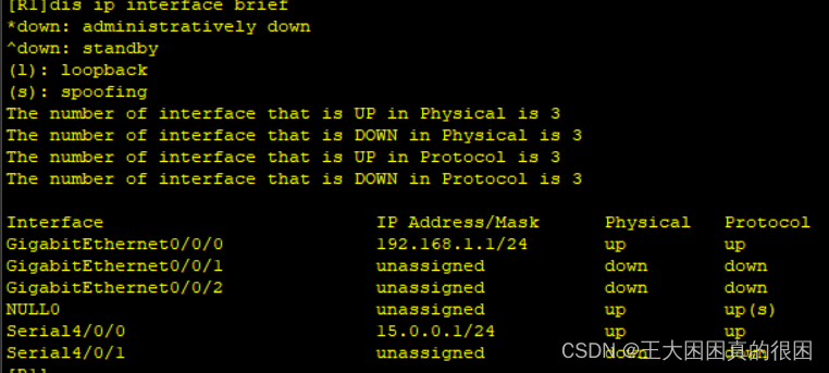
查看接口状况 up证明协商成功
R1和R5之间使用ppp的chap认证且R5为主认证方
- [ISP]int s3/0/1
- [ISP-Serial3/0/1]link-pro ppp
- [ISP-Serial3/0/1]ppp au
- [ISP-Serial3/0/1]ppp authentication-mode chap
- [ISP-Serial3/0/1]q
-
- [R2]int s4/0/0
- [R2-Serial4/0/0]link-type ppp
- ^
- Error: Unrecognized command found at '^' position.
- [R2-Serial4/0/0]link-pro ppp
- [R2-Serial4/0/0]ppp chap user huawei
- [R2-Serial4/0/0]ppp chap password c
- [R2-Serial4/0/0]ppp chap password cipher 123456
- [R2-Serial4/0/0]
- [R2-Serial4/0/0]
- [R2-Serial4/0/0]shutdown
- Jan 25 2024 12:44:01-08:00 R2 %%01IFPDT/4/IF_STATE(l)[10]:Interface Serial4/0/0
- has turned into DOWN state.
- [R2-Serial4/0/0]
- [R2-Serial4/0/0]undo shutdown
- [R2-Serial4/0/0]
- Jan 25 2024 12:44:17-08:00 R2 %%01IFPDT/4/IF_STATE(l)[11]:Interface Serial4/0/0
- has turned into UP state.
- [R2-Serial4/0/0]q
- [R2]

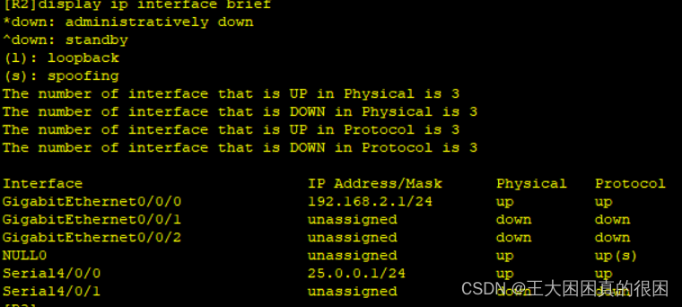
协商成功
R3和R5之间使用HDLC封装
- [ISP]interface Serial 4/0/0
- [ISP-Serial4/0/0]link-pro hdlc
- Warning: The encapsulation protocol of the link will be changed. Continue? [Y/N]
- :y
- Jan 25 2024 12:49:39-08:00 ISP %%01IFNET/4/CHANGE_ENCAP(l)[7]:The user performed
- the configuration that will change the encapsulation protocol of the link and t
- hen selected Y.
- [ISP-Serial4/0/0]
- [R3]int s4/0/0
- [R3-Serial4/0/0]link-pro hdlc
- Warning: The encapsulation protocol of the link will be changed. Continue? [Y/N]
- :y
- Jan 25 2024 12:51:21-08:00 R3 %%01IFNET/4/CHANGE_ENCAP(l)[7]:The user performed
- the configuration that will change the encapsulation protocol of the link and th
- en selected Y.
- [R3-Serial4/0/0]
- [R3-Serial4/0/0]shutdown
- Jan 25 2024 12:51:26-08:00 R3 %%01IFPDT/4/IF_STATE(l)[11]:Interface Serial4/0/0
- has turned into DOWN state.
- [R3-Serial4/0/0]
- [R3-Serial4/0/0]
- Jan 25 2024 12:51:26-08:00 R3 %%01IFNET/4/LINK_STATE(l)[12]:The line protocol IP
- on the interface Serial4/0/0 has entered the DOWN state.
- [R3-Serial4/0/0]
- [R3-Serial4/0/0]undo shutdown
- [R3-Serial4/0/0]
- Jan 25 2024 12:51:35-08:00 R3 %%01IFPDT/4/IF_STATE(l)[13]:Interface Serial4/0/0
- has turned into UP state.
- [R3-Serial4/0/0]
- Jan 25 2024 12:51:35-08:00 R3 %%01IFNET/4/LINK_STATE(l)[14]:The line protocol IP
- on the interface Serial4/0/0 has entered the UP state.
- [R3-Serial4/0/0]

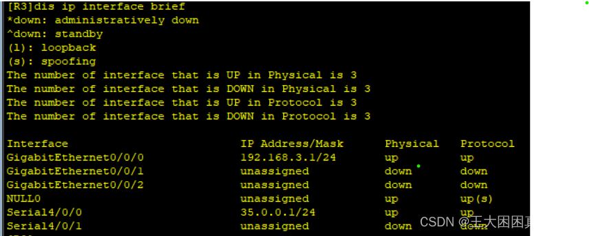
成功
三、物理链路PC访问公网
- [R1]ip route-static 0.0.0.0 0 15.0.0.2
-
- [R1]acl 2000
- [R1-acl-basic-2000]rule permit source 192.168.1.0 0.0.0.255
- [R1-acl-basic-2000]q
- [R1]int s4/0/0
- [R1-Serial4/0/0]nat outbound 2000
- [R1-Serial4/0/0]q
- [R1]
- [R2]ip route-static 0.0.0.0 0 25.0.0.2
- [R2]
- [R2]acl 2000
- [R2-acl-basic-2000]rule permit source 192.168.2.0 0.0.0.255
- [R2-acl-basic-2000]q
- [R2]int s4/0/0
- [R2-Serial4/0/0]nat outbound 2000
- [R2-Serial4/0/0]q
- [R3]ip route-static 0.0.0.0 0 35.0.0.2
- [R3]
- [R3]acl 2000
- [R3-acl-basic-2000]rule permit source 192.168.3.0 0.0.0.255
- [R3-acl-basic-2000]q
- [R3]int s4/0/0
- [R3-Serial4/0/0]nat outbound 2000
- [R3-Serial4/0/0]q
- [R4]ip route-static 0.0.0.0 0 45.0.0.2
- [R4]
- [R4]acl 2000
- [R4-acl-basic-2000]rule permit source 192.168.4.0 0.0.0.255
- [R4-acl-basic-2000]q
- [R4]int g0/0/1
- [R4-GigabitEthernet0/0/1]nat outbound 2000
- [R4-GigabitEthernet0/0/1]q
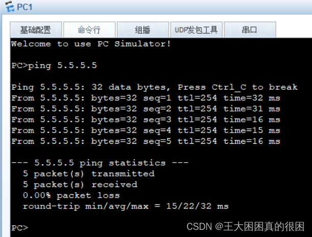
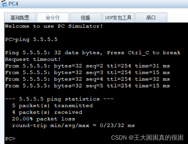
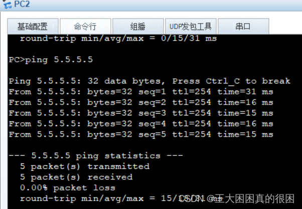
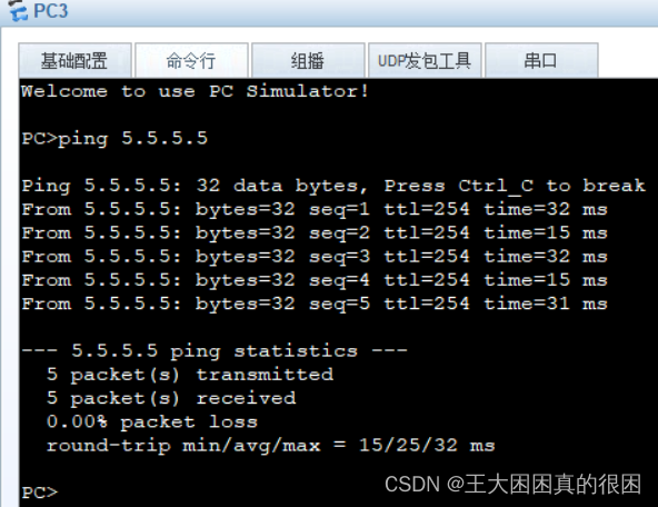
全部成功!
四、mgre
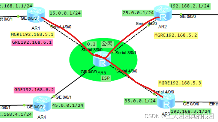
R1为中心,R2、R3为分支
- [R1]
- [R1]int tunnel 0/0/0
- [R1-Tunnel0/0/0]ip add 192.168.5.1 24
- [R1-Tunnel0/0/0]tunnel-protocol gre p2mp
- [R1-Tunnel0/0/0]source 15.0.0.1
- Jan 25 2024 13:20:07-08:00 R1 %%01IFNET/4/LINK_STATE(l)[0]:The line protocol IP
- on the interface Tunnel0/0/0 has entered the UP state.
- [R1-Tunnel0/0/0]
- [R1-Tunnel0/0/0]nhrp network-id 100
- [R1-Tunnel0/0/0]q
- [R2]int t0/0/0
- [R2-Tunnel0/0/0]ip add 192.168.5.2 24
- [R2-Tunnel0/0/0]tunnel-protocol gre p2mp
- [R2-Tunnel0/0/0]source s4/0/0
- Jan 25 2024 13:24:06-08:00 R2 %%01IFNET/4/LINK_STATE(l)[0]:The line protocol IP
- on the interface Tunnel0/0/0 has entered the UP state.
- [R2-Tunnel0/0/0]nhrp network-id 100
- [R2-Tunnel0/0/0]nhrp entry 192.168.5.1 15.0.0.1 r
- [R2-Tunnel0/0/0]nhrp entry 192.168.5.1 15.0.0.1 register
- [R2-Tunnel0/0/0]q
- [R3]int t0/0/0
- [R3-Tunnel0/0/0]tunnel-protocol gre p2mp
- [R3-Tunnel0/0/0]ip add 192.168.5.3 24
- [R3-Tunnel0/0/0]source 35.0.0.1
- Jan 25 2024 13:28:31-08:00 R3 %%01IFNET/4/LINK_STATE(l)[0]:The line protocol IP
- on the interface Tunnel0/0/0 has entered the UP state.
- [R3-Tunnel0/0/0]
- [R3-Tunnel0/0/0]nhrp network-id 100
- [R3-Tunnel0/0/0]nhrp entry 192.168.5.1 15.0.0.1 register
- [R3-Tunnel0/0/0]q
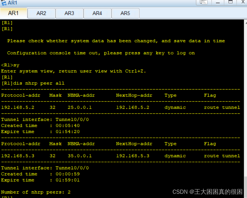
中心获取到了这样一个nhrp表


r2r3都有去往中心的
两个分支之间没有,且主机之间仍不能相互访问因为路由表不全,随后我们解决这个问题。
五、gre
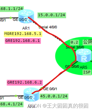
R1和R4之间为点到点的GRE
- [R1]int tunnel0/0/1
- [R1-Tunnel0/0/1]ip add 192.168.6.1 24
- [R1-Tunnel0/0/1]tunnel-protocol gre
- [R1-Tunnel0/0/1]source 15.0.0.1
- [R1-Tunnel0/0/1]de
- [R1-Tunnel0/0/1]destination 45.0.0.1
- Jan 25 2024 13:40:04-08:00 R1 %%01IFNET/4/LINK_STATE(l)[0]:The line protocol IP
- on the interface Tunnel0/0/1 has entered the UP state.
- [R1-Tunnel0/0/1]
- [R1-Tunnel0/0/1]q
- [R4]int t0/0/1
- [R4-Tunnel0/0/1]ip add 192.168.6.2 24
- [R4-Tunnel0/0/1]tunnel-pro gre
- [R4-Tunnel0/0/1]source 45.0.0.1
- [R4-Tunnel0/0/1]destination 15.0.0.1
- Jan 25 2024 13:42:04-08:00 R4 %%01IFNET/4/LINK_STATE(l)[0]:The line protocol IP
- on the interface Tunnel0/0/1 has entered the UP state.
- [R4-Tunnel0/0/1]
- [R4-Tunnel0/0/1]q
此时主机之间还是不能访问,两个直连接口可以通。因为没有互相路由
[R4]ip route-static 192.168.1.0 24 192.168.6.1
[R1]ip route-static 192.168.4.0 24 192.168.6.2再次测试
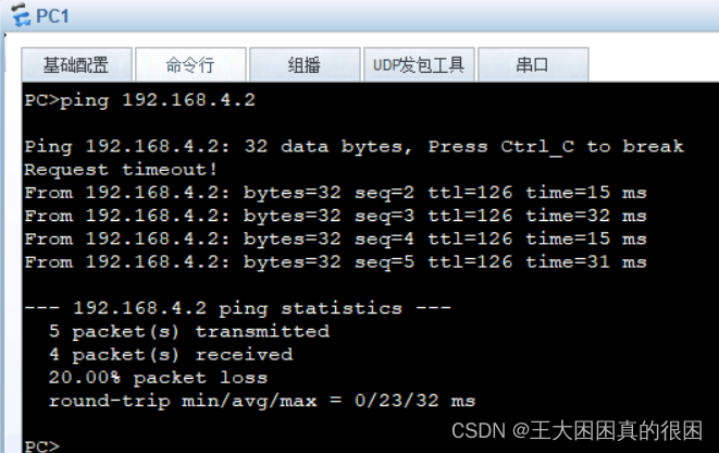
pc1成功访问pc4
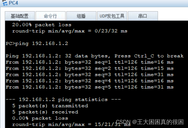
pc4成功访问pc1
gre环境建立成功
六、私有网络基于RIP全网可达
- [R1]rip 1
- [R1-rip-1]ver 2
- [R1-rip-1]network 192.168.1.0
- [R1-rip-1]network 192.168.6.0
- [R1-rip-1]q
- [R1]rip 1
- [R1-rip-1]network 192.168.5.0
- [R1-rip-1]q
- [R2]rip 1
- [R2-rip-1]ver 2
- [R2-rip-1]network 192.168.2.0
- [R2-rip-1]network 192.168.5.0
- [R2-rip-1]q
- [R3]rip 1
- [R3-rip-1]ver 2
- [R3-rip-1]network 192.168.3.0
- [R3-rip-1]network 192.168.5.0
- [R3-rip-1]q
- [R4]rip 1
- [R4-rip-1]ver 2
- [R4-rip-1]network 192.168.4.0
- [R4-rip-1]network 192.168.6.0
- [R4-rip-1]q
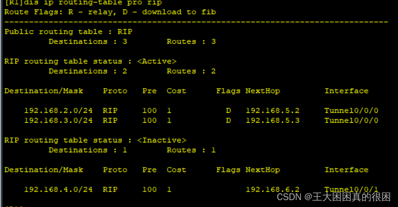
R1的路由表是全的

R2上查不到,R3上也查不到

解决分支无路由表情况
一吧gre环境改变为多播,二把rip水平分割机制关闭
- [R1]int t0/0/0
- [R1-Tunnel0/0/0]nhrp entry mu
- [R1-Tunnel0/0/0]nhrp entry multicast dy
- [R1-Tunnel0/0/0]nhrp entry multicast dynamic
- [R1-Tunnel0/0/0]
- [R1-Tunnel0/0/0]q
- [R1]
- [R1]int t0/0/0
- [R1-Tunnel0/0/0]undo rip split
- [R1-Tunnel0/0/0]undo rip split-horizon
- [R1-Tunnel0/0/0]
- [R1-Tunnel0/0/0]
- [R1-Tunnel0/0/0]q
- [R1]
七、发现问题
我们来查看一下路由表
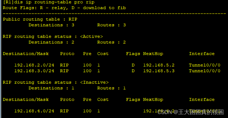
通向r4的rip为非活跃
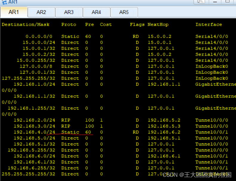
是因为静态路由的优先级更高
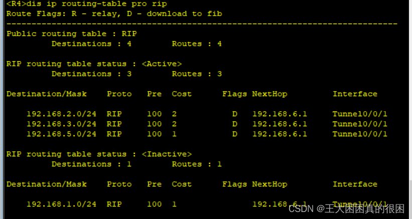

在R4上也一样静态优先
这说明,R1 与R4的主机相互访问没有问题, R1R2R3的主机相互访问没有问题
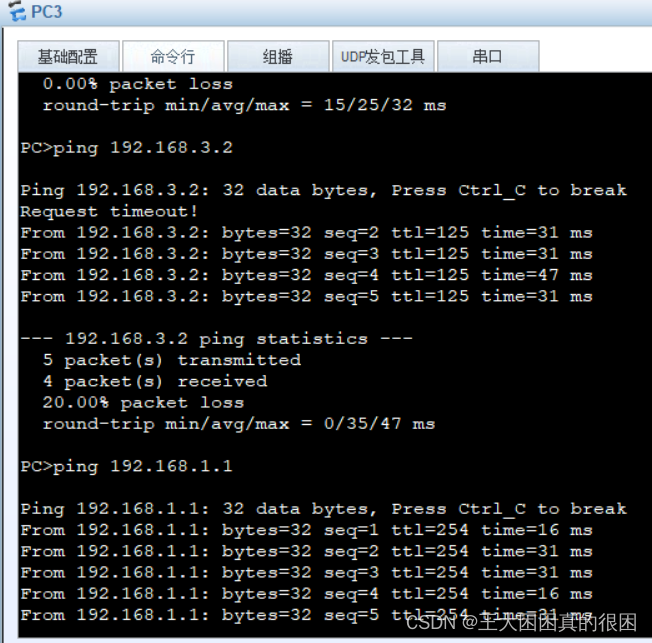
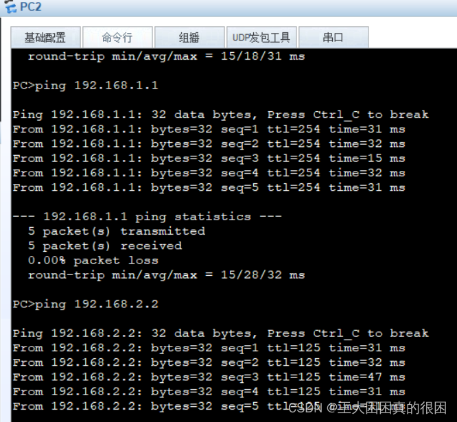
pc1/pc2/pc3相互访问没有问题
问题在于,正常应该全网可通,但是如下图
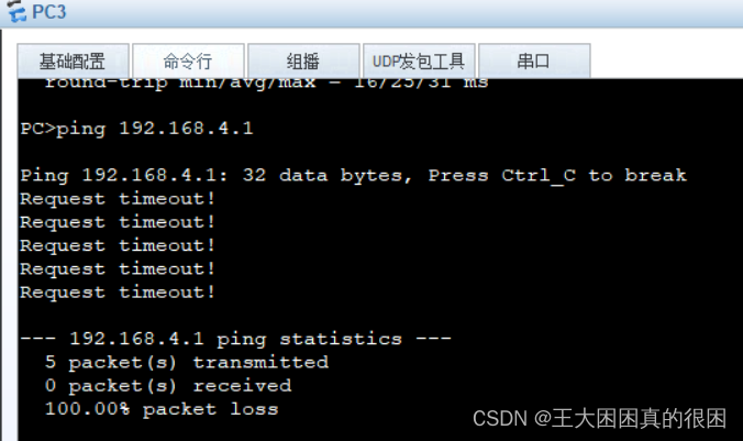
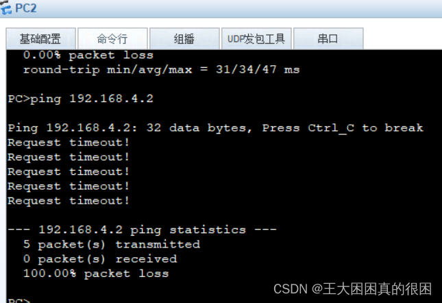
4.0网段不能与2.0、3.0网段互通,即使R4的路由表里有2.0与3.0网段,但是发现R2、R3的路由表里没有4.0网段
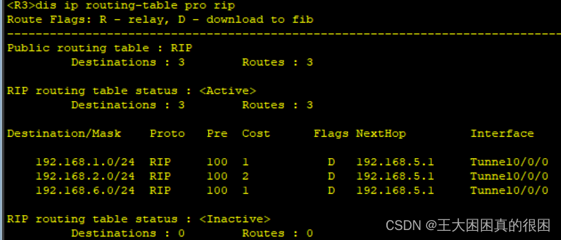
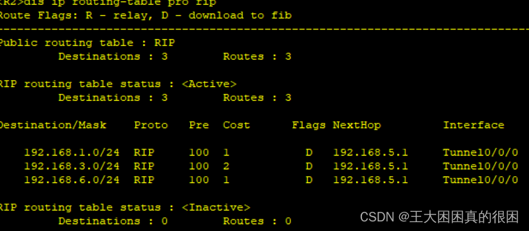
明明宣告都没有问题,为什么会这样?
正是因为静态路由的优先级比RIP优先级高,R1作为中心,把学习来的路由表共享给分支R2和R3,R1路由表里静态配置的4.0网段并不是通过RIP学习得来,R1并没有把4.0网段分享给R2和R3。
当我们将R1上通往R4的静态路由拿掉
[R1]undo ip route-static 192.168.4.0 255.255.255.0 192.168.6.2 路由表更新,通向R4为RIP学习
对于R4并没有影响
再次查看r2和r3路由表
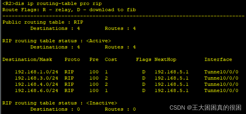
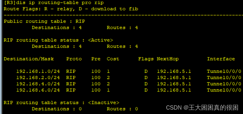
路由表里有了R1分享来的4.0网段
检测
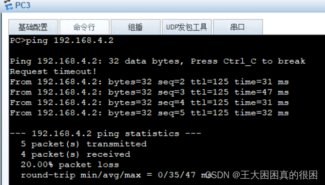
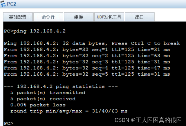
成功达到全网互通!!
总结
本次实验要求直接的关联性并不大,每一个点都是可以单独进行学习的,放在一起考察配置,可以发现某一块问题还是很清晰的。本次的重要是GRE环境与MGER环境 的工作原理,数据包的封装,和配置思路,最终实现全网可达。
没什么问题了叭。。。
这次没有可指正的错误,欢迎提问
拜拜~~~~


