
- 1记录错误1——edge浏览器兼容性问题_edge兼容性问题文件winhafnt
- 2FPGA搭建NVMe读写硬盘系统:通过PCIe模块实现CPU对硬盘的操作,以XC7Z100为核心的架构实现PL与硬盘的连接_fpga pcie
- 32024年最新微服务高并发秒杀实战_基于令牌桶实现库存_库存高并发实现
- 4MySQL基础之触发器,函数,存储过程_mysql触发器调用存储过程
- 5《Android Studio 项目上传到Git》_android studio上传项目到git
- 6【鸿蒙千帆起】米哈游、网易等官宣加入,“鸿蒙“为何是游戏圈年度关键词?
- 7基于FPGA的俄罗斯方块设计_fpga俄罗斯方块
- 8C和指针之反转字符串_he c网打开反转
- 9应用式数据库 VS 集成式数据库
- 10【华为OD机试真题2023C&D卷 JAVA&JS】小明找位置
[Simulink] 从Simulink S函数的使用_simulink如何使用printf的格式
赞
踩
Simulink S函数的使用
这部分涉及到对Simulink建模的控制,从而生成我们可读、可进一步编写或修改的代码。因此,建模时需要遵循一定的建模规范,并进行对应的检查,例如:ISO26262、MAAB、MISRA C等检查,MAAB的建模规范中给出很多建模注意事项,为了满足代码的可读性,可以利用Simlink的mpt数据类型建立对应的数据字典。
这部分不是这个学习笔记的重点,这里先挖坑。
Simulink C Mex S Function
制作C MEX S函数,代码如下:
#define S_FUNCTION_NAME digital_in /* Defines and Includes */
#define S_FUNCTION_LEVEL 2

#include "simstruc.h"

enum{
    Pin_idx = 0,
    N_Para
};

#define Pin(S) mxGetScalar(ssGetSFcnParam(S,Pin_idx))

static void mdlInitializeSizes(SimStruct *S)
{
    ssSetNumSFcnParams(S, N_Para);
    if (ssGetNumSFcnParams(S) != ssGetSFcnParamsCount(S)) {
        return; /* Parameter mismatch reported by the Simulink engine*/
    }

    ssSetSFcnParamNotTunable(S,0);

    if (!ssSetNumInputPorts(S, 1)) return;
    ssSetInputPortWidth(S, 0, 1);
    ssSetInputPortDirectFeedThrough(S, 0, 1);

    if (!ssSetNumOutputPorts(S,0)) return; /*ssSetOutputPortWidth(S, 0, DYNAMICALLY_SIZED);*/

    ssSetNumSampleTimes(S, 1);

    /* Take care when specifying exception free code - see sfuntmpl.doc */
    ssSetOptions(S, SS_OPTION_EXCEPTION_FREE_CODE);
    }
static void mdlInitializeSampleTimes(SimStruct *S)
{
    ssSetSampleTime(S, 0, INHERITED_SAMPLE_TIME);
    ssSetOffsetTime(S, 0, 0.0);
}
static void mdlOutputs(SimStruct *S, int_T tid)
{
}
static void mdlTerminate(SimStruct *S){}

#define MDL_RTW
static void mdlRTW(SimStruct *S){
    int8_T pin_number = Pin(S);
    if(!ssWriteRTWParamSettings(S,N_Para,
            SSWRITE_VALUE_DTYPE_NUM,"PIN", &pin_number, DTINFO(SS_INT8, COMPLEX_NO) ))
    return;

}


#ifdef MATLAB_MEX_FILE /* Is this file being compiled as a MEX-file? */
#include "simulink.c" /* MEX-file interface mechanism */
#else
#include "cg_sfun.h" /* Code generation registration function */
#endif

- 1
- 2
- 3
- 4
- 5
- 6
- 7
- 8
- 9
- 10
- 11
- 12
- 13
- 14
- 15
- 16
- 17
- 18
- 19
- 20
- 21
- 22
- 23
- 24
- 25
- 26
- 27
- 28
- 29
- 30
- 31
- 32
- 33
- 34
- 35
- 36
- 37
- 38
- 39
- 40
- 41
- 42
- 43
- 44
- 45
- 46
- 47
- 48
- 49
- 50
- 51
- 52
- 53
- 54
- 55
- 56
- 57
- 58
上述代码中,两个地方注意一下:
enum{
    Pin_idx = 0,
    N_Para
};
- 1
- 2
- 3
- 4
其中,
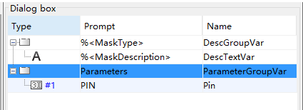
enum枚举了两个变量Pin_idx和N_Para,其中初始化Pin_idx= 0,则N_Para就初始化为1,恰好与变量个数相对应。#define Pin(S) mxGetScalar(ssGetSFcnParam(S,Pin_idx))获取参数,获取到的是具体的值,这里需要将S-Function中的Parameters对应好。ssWriteRTWParamSettings这个是要进行参数的传递,需要注意的是最终RTW认的是用户设定的参数名,而不是上图中的S-function parameters填写的参数,即:
if(!ssWriteRTWParamSettings(S,N_Para,
            SSWRITE_VALUE_DTYPE_NUM,"PIN", &pin_number, DTINFO(SS_INT8, COMPLEX_NO) ))
    return;
- 1
- 2
- 3
最终的tlc控制.c文件的时候,用的是"PIN"这个参数名,而不是Pin。
digital_in.c --> digital_in.mexw64
我使用的是windows 64位的电脑,所以生成的是digital_in.mexw64的文件,windows 32位则生成digital_in.mexw32的文件。
在Command Windows中键入:
mex digital_in.c
- 1
编写digital_in.tlc
编写tlc文件要实现的目的是:
将Simulink模块与最终的代码实现有效地结合,即生成可以直接进行编译的代码。
这里的tlc主要实现:
- 在model.c文件的Includes部分加入
#include "reg52.h",在model_step()函数中加入P%<Pin> = %<u>; - 为了说明如何生成用户自定义的文件,这里生成一个GPIOconfig.c文件,里面什么也没有。
代码如下:
%implements digital_in "C"


%%assign u = LibBlockInputSignal(0, "","",0)

%function BlockTypeSetup(block, system) void
	%% 初始化程序写入到ert_main.c中?
	%openfile tmpBuf
		#include "reg52.h"
	%closefile tmpBuf
	%assign srcFile = LibGetModelDotCFile()
    %warning srcFile
	%<LibSetSourceFileSection(srcFile, "Includes", tmpBuf)>

    %openfile tmpBuf

    %closefile tmpBuf
    %assign cFile = LibCreateSourceFile("Source","Custom","GPIOconfig")
    %<LibSetSourceFileSection(srcFile, "Defines", tmpBuf)>
%endfunction

%function BlockInstanceSetup(block, system) void
%endfunction

%function Outputs(block, system) Output
%assign u = LibBlockInputSignal(0, "","",0)
%assign Pin = CAST("Number", SFcnParamSettings.PIN)
P%<Pin> = %<u>;
%endfunction
- 1
- 2
- 3
- 4
- 5
- 6
- 7
- 8
- 9
- 10
- 11
- 12
- 13
- 14
- 15
- 16
- 17
- 18
- 19
- 20
- 21
- 22
- 23
- 24
- 25
- 26
- 27
- 28
- 29
- 30
- 31

建立S-function模块
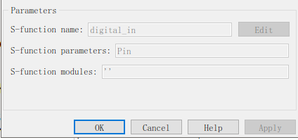
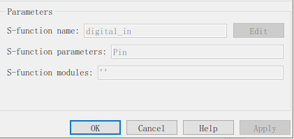
建立S-function模块,并Mask掉,参数如下:
在S-function模块中填入
因为这里没有对digital_in.c中的mdlOuputs函数进行内容的填写,所以仿真时是没有任何输出的。
配置环境
配置ert.tlc,设置为Fixed-step,进行自动代码生成,生成后的代码中标黄的地方为用户自定义的部分

编译
在编译之前,对ert_main.c进行修改:
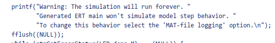
- 删除掉
#include <stdio.h> /* This ert_main.c example uses printf/fflush */ int_T main(int_T argc, const char *argv[])修改为int_T main(void),同时删除(void)(argc); (void)(argv);- 删除下图中部分:
- 将
rt_OneStep()放到while (rtmGetErrorStatus(LED_demo_M) == (NULL))中 - 在
rt_OneStep()的/* Enable interrupts here */部分添加一个时钟中断
上面的修改其实可以看出,要做一个合适的底层驱动,其实最好是自定义main文件
这里给一个自己修改的ert_main.c
/*
 * File: ert_main.c
 *
 * Code generated for Simulink model 'LED'.
 *
 * Model version                  : 1.1
 * Simulink Coder version         : 9.0 (R2018b) 24-May-2018
 * C/C++ source code generated on : Fri Apr 12 10:31:58 2019
 *
 * Target selection: ert.tlc
 * Embedded hardware selection: Intel->x86-64 (Windows64)
 * Code generation objectives: Unspecified
 * Validation result: Not run
 */

#include <stddef.h>
#include "LED.h"                       /* Model's header file */
#include "rtwtypes.h"
/*#include "reg52.h"

/*#define led_blink P0

/*
 * Associating rt_OneStep with a real-time clock or interrupt service routine
 * is what makes the generated code "real-time".  The function rt_OneStep is
 * always associated with the base rate of the model.  Subrates are managed
 * by the base rate from inside the generated code.  Enabling/disabling
 * interrupts and floating point context switches are target specific.  This
 * example code indicates where these should take place relative to executing
 * the generated code step function.  Overrun behavior should be tailored to
 * your application needs.  This example simply sets an error status in the
 * real-time model and returns from rt_OneStep.
 */

typedef unsigned int u16;

void delay(u16 i)
{
	while(i--);
}

void rt_OneStep(void);
void rt_OneStep(void)
{
  static boolean_T OverrunFlag = false;

  /* Disable interrupts here */

  /* Check for overrun */
  if (OverrunFlag) {
    rtmSetErrorStatus(LED_M, "Overrun");
    return;
  }

  OverrunFlag = true;

  /* Save FPU context here (if necessary) */
  /* Re-enable timer or interrupt here */
  /* Set model inputs here */

  /* Step the model */
  LED_step();

  /* Get model outputs here */
	/*led_blink = LED_Y.Out1;
  /* Indicate task complete */
  OverrunFlag = false;

  /* Disable interrupts here */
  /* Restore FPU context here (if necessary) */
  /* Enable interrupts here */
	delay(100000);
}

/*
 * The example "main" function illustrates what is required by your
 * application code to initialize, execute, and terminate the generated code.
 * Attaching rt_OneStep to a real-time clock is target specific.  This example
 * illustrates how you do this relative to initializing the model.
 */
int_T main(void)
{

  /* Initialize model */
  LED_initialize();

  /* Attach rt_OneStep to a timer or interrupt service routine with
   * period 1.0 seconds (the model's base sample time) here.  The
   * call syntax for rt_OneStep is
   *
   rt_OneStep();
   */


  while (rtmGetErrorStatus(LED_M) == (NULL)) {
    /*  Perform other application tasks here */
		rt_OneStep();
  }

  /* Disable rt_OneStep() here */

  /* Terminate model */
  LED_terminate();
  return 0;
}

/*
 * File trailer for generated code.
 *
 * [EOF]
 */
- 1
- 2
- 3
- 4
- 5
- 6
- 7
- 8
- 9
- 10
- 11
- 12
- 13
- 14
- 15
- 16
- 17
- 18
- 19
- 20
- 21
- 22
- 23
- 24
- 25
- 26
- 27
- 28
- 29
- 30
- 31
- 32
- 33
- 34
- 35
- 36
- 37
- 38
- 39
- 40
- 41
- 42
- 43
- 44
- 45
- 46
- 47
- 48
- 49
- 50
- 51
- 52
- 53
- 54
- 55
- 56
- 57
- 58
- 59
- 60
- 61
- 62
- 63
- 64
- 65
- 66
- 67
- 68
- 69
- 70
- 71
- 72
- 73
- 74
- 75
- 76
- 77
- 78
- 79
- 80
- 81
- 82
- 83
- 84
- 85
- 86
- 87
- 88
- 89
- 90
- 91
- 92
- 93
- 94
- 95
- 96
- 97
- 98
- 99
- 100
- 101
- 102
- 103
- 104
- 105
- 106
- 107
- 108
- 109
- 110
- 111
- 112
接下来就是可以keil进行编译,生成hex文件,并通过烧录软件烧写程序了,这部分就不说了。
总结
上面的过程,实际上是利用S函数和tlc来控制代码的过程,实际上S函数还可以实现C代码的嵌入需求,好像 C Caller这个模块也行。

