- 1打造个性化github主页 二 WakaTime - 动态统计你的工作量_怎么通过wakatime美化github
- 2树莓派科学小实验4B--08_倾斜传感器、干簧管、震动传感器_三个传感器树莓派实验
- 3OPENCV面试题
- 4CTF之逆向Reverse入门推荐学习知识点总结面向新手小白_ctf reverse
- 5springboot集成sse实现后端流式输出消息_springboot流式
- 6Android开发—基于OpenCV实现相机实时图像识别跟踪,入职3个月的Android程序员面临转正_opencv实时图像追踪
- 7小程序云函数调用_小程序云函数抓包
- 86个超级实用的免费网盘搜索网站分享_盘131
- 9遍历HashMap的五种方式_hashmap遍历
- 10kafka基础知识
基于采样的路径规划算法RRT和代码实现_路径规划状态采样算法有哪些
赞
踩
前言
本文主要介绍快速扩展随机树算法(RRT)以及改进的RRT*算法,同时讲解在ROS中实现RRT算法。在正文之前,在前言中讲一个需要知道的概念。
规划器的完备性:能够在指定的时间内规划出一条正确的路径;
规划器概率的完备性:如果能行走通的路径存在,规划器一定能够基于随机采样算法找到它;
规划器解决方案完备性:如果能行走通的路径存在,规划器一定能够基于确定性采样方法找到它;
一、概率路图法
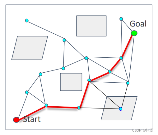
概率路图法是一种构建有效路径图的方法,能够解决高维空间构造有效路径图的困难,它分为学习和查询两个阶段,下面通过介绍它的采样和搜索来详细介绍概率路图法。
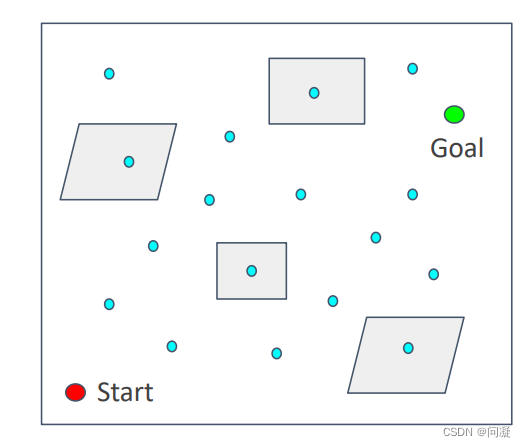
1.1 采样阶段
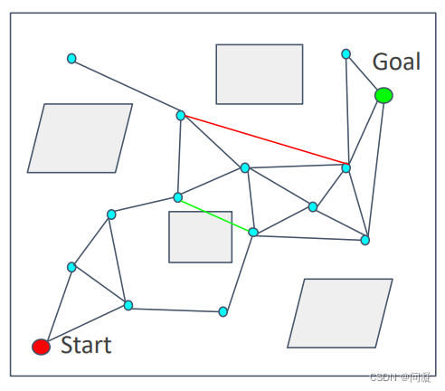
1)在环境中以某种策略采样N个点,比如以均匀方式在环境采样N个点;
2)去除在障碍物内部的点;
3)将点连接到离自身比较近的点上;
4)删除穿过障碍物的点;
1.2 搜索阶段
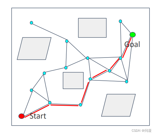
从构建好的图中采用Dijkstra算法或A*算法搜索从起点到终点的可执行路径。
1.3 Lazy collision-checking
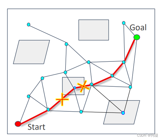
1)为了提升概率路图法的效率,在概率路图法的基础上加入了Lazy collision-checking策略,这个策略的思想是在环境中采样得到N个点后,不去删除在障碍物内部的点,因为如果环境障碍物很多,采样到障碍物内部的点比较多的话,删除障碍物内部的点会比较费时而且不是规划的路径要经过所有的障碍物,删除所有的障碍物内的点就比较冗余了;
2)不删除所有的障碍物内的点,直接利用构建好的图搜索路径,当碰到障碍物时,删除对应的边,重新寻找路径,直到到达终点。
二、快速扩展随机树
2.1 RRT算法流程
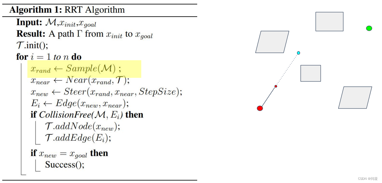 上图的伪代码给出了一下RRT算法的流程,我再来详细的介绍一下:
首先,因为是要扩展随机树,所以要生成树,在最开始的时候需要先采样一个点,然后连接起点和这个点,如果这条路是collision-free的,那么就沿着这个方向走stepsize的距离,然后把小红圈的节点以及那条边加到树中,从而构成了一棵树;
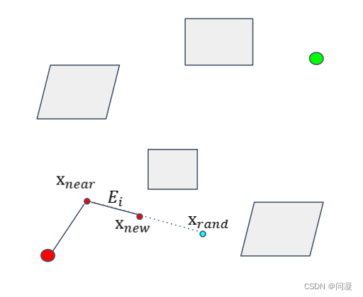
来看循环的逻辑,实际上上面的一步也是循环的逻辑,只是为了理解方便,把构建一棵树的过程单独说一下,然后再看循环会更加清楚一点;循环中第一步是在环境中采样一些点,比如以Xrand点为采样的点,找树中离它最近的点,就找到了Xnear,如果连接Xnear和Xrand的边是collision-free的,那么就沿着这个方向走stepsize的距离,然后把边Ei和节点Xnew加入树中,完成了一次树的扩展;如此一直循环扩展随机树,直到扩展到了目标节点或者说是终点,那就停止扩展,从终点开始寻找父节点,从而找到了一条从起点到终点的路径。
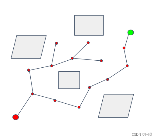
RRT算法的优点是能够从起点找到一条到终点的路径,而且比PRM算法更具有目标性;它的缺点是不一定是最优路径,而且连接节点之间的连接是直线,不太适合机器人执行,而且也不是那么的高效,并且是在整个空间进行采样。
2.2 RRT 算法改进
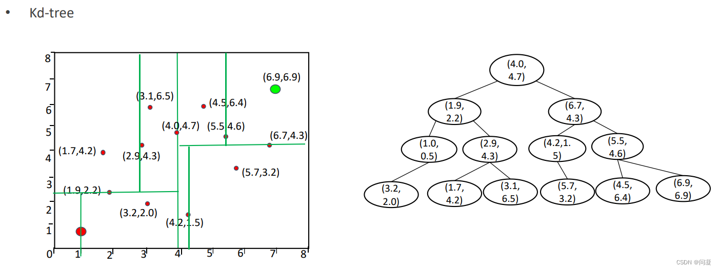
1)用Kd树帮助RRT算法找到离Xrand最近的节点Xnear,把所有的节点用Kd树的格式保存,那得到一个新的节点后我们就可以用Kd树这个算法来帮助我们找到最近的点Xnear;
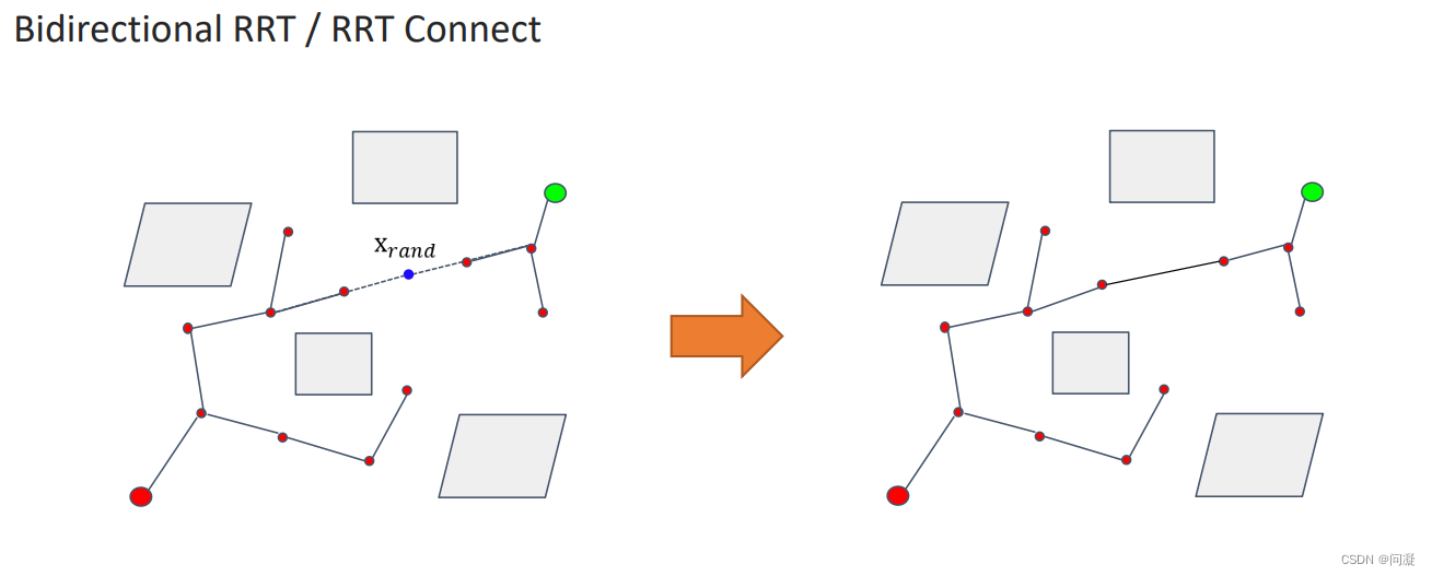
2)双向RRT算法:上面讲的要构建一棵树是从起点开始搜索构建一棵树;现在RRT connect为了提升效率,我们从起点和终点同时开始搜索构建两棵树,撒一次点实现两棵树的构建,当Xrand同时连接两棵树的时候,两棵树生长结束,那么我们就找到了起点到终点的一个路径。
2.3 RRT* 算法

RRT* 算法与RRT算法在寻找Xrand、Xnear、Xnew这几个节点是一样的,RRT算法是直接连接Xnear和Xnew完成一次树的扩展,但是在RRT *算法中有一些不同,RRT *算法在Xnew附近以r为半径,找到它的在圆里的节点作为最近节点;首先Xnear、X1、X2都通过直接与Xnew连接起来,算一下起点到Xnew通过Xnear、X1、X2哪一个路径花费最小,这个时候它们三个中路径最小的就是Xnew的父节点,连接Xnew和Xnew的父节点,完成了一次树的扩展;
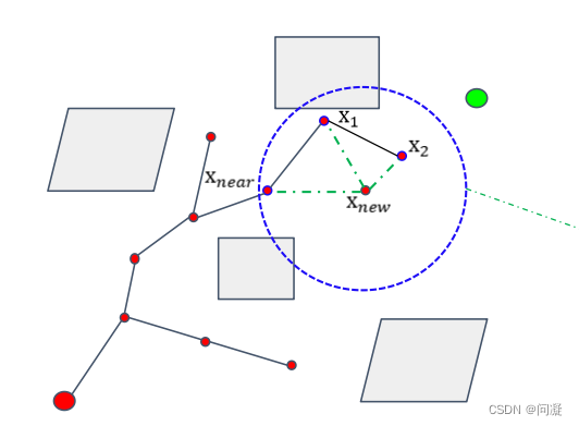
还有一个不同的地方在于RRT* 算法的rewire(对树的修正),Xnew添加到树之后,(因为这个例子中Xnear是Xnew的父节点,才连接Xnew与X1和X2,如果其他节点是Xnew的节点,就连接Xnew与它附近以r为半径的圆里的非其父节点的其他节点),连接Xnew与X1和X2,计算X1、X2和起点之间的距离,如果通过Xnew到起点的距离小于通过其他节点到达起点的距离,那么就修改X1和X2的父节点为Xnew;这个过程不断迭代,从而使路径更加优化;RRT* 算法会对树持续的优化,因此比RRT算法更加高效。
2.4 Kinodynamic RRT* 算法

改变连接Xnew和Xnear的方式,不再是用一条直线,而是一条考虑机器人的运动学约束的执行比较平稳的路径,使得机器人运动更加平滑。
2.4 Informed RRT* 算法
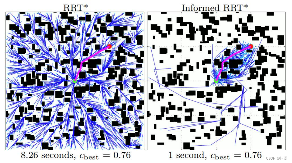
RRT* 算法找到了一条从起点到终点的路径后,还对路径进行持续改进,但是RRT* 算法是在整个空间进行对树进行重构,我们其实只是希望对路径进行优化;Informed RRT* 算法把采样的过程限制在椭圆里面,椭圆是围绕生成的路径产生的(以起点和终点为焦点,以路径的长度作为任意一个椭圆点到两个焦点的距离),从而只是对路径进行优化,Informed RRT* 算法是基于提高采样效率,改进采样方式对RRT* 算法进行了改进。
三、RRT* 算法代码
3.1 ompl库的要求
要学会调⽤ompl 实现 RRT*,需要实现的功能如下:
1.把⽤户定义的起点、终点、地图⽤ompl 库定义的数据结构表⽰;
2.了解 ompl 调⽤RRT*的⽅法和步骤;
3.把 ompl 库求解得到的路径转换为⽤户定义的数据结构;
3.2 RRT* 算法代码
1)第一步是在机器人的状态空间中找机器人的状态信息;
// Our collision checker. For this demo, our robot's state space
class ValidityChecker : public ob::StateValidityChecker
{
public:
    ValidityChecker(const ob::SpaceInformationPtr& si) :
        ob::StateValidityChecker(si) {}
    // Returns whether the given state's position overlaps the
    // circular obstacle
    bool isValid(const ob::State* state) const
    {
        // We know we're working with a RealVectorStateSpace in this
        // example, so we downcast state into the specific type.
        // space为三维的状态空间,si为状态的信息
        const ob::RealVectorStateSpace::StateType* state3D =
            state->as<ob::RealVectorStateSpace::StateType>();
        /**
        *
        *
        STEP 1: Extract the robot's (x,y,z) position from its state
        *
        *
        */
       double x, y, z;
       x = (*state3D)[0];
       y = (*state3D)[1];
       a = (*state3D)[2];

        return _RRTstar_preparatory->isObsFree(x, y, z);
    }
};
- 1
- 2
- 3
- 4
- 5
- 6
- 7
- 8
- 9
- 10
- 11
- 12
- 13
- 14
- 15
- 16
- 17
- 18
- 19
- 20
- 21
- 22
- 23
- 24
- 25
- 26
- 27
- 28
- 29
- 30
2)设置起点和终点信息,同时构造pathfinding问题的实例;
void pathFinding(const Vector3d start_pt, const Vector3d target_pt)
{
    // Construct the robot state space in which we're planning.
    // 通过ob里的RealVectorStateSpace(3)构造出一个三维的状态空间
    ob::StateSpacePtr space(new ob::RealVectorStateSpace(3));

    // Set the bounds of space to be in [0,1].
    // 设置状态空间的边界
    ob::RealVectorBounds bounds(3);
    bounds.setLow(0, - _x_size * 0.5);
    bounds.setLow(1, - _y_size * 0.5);
    bounds.setLow(2, 0.0);

    bounds.setHigh(0, + _x_size * 0.5);
    bounds.setHigh(1, + _y_size * 0.5);
    bounds.setHigh(2, _z_size);

    // 将设置的边界赋予状态空间space,其中as的作用是类型转换
    space->as<ob::RealVectorStateSpace>()->setBounds(bounds);
    //  构造状态空间信息
    // Construct a space information instance for this state space
    ob::SpaceInformationPtr si(new ob::SpaceInformation(space));
    // Set the object used to check which states in the space are valid
    // 为状态空间设置状态检查函数StateValidChecker,si为状态的信息
    si->setStateValidityChecker(ob::StateValidityCheckerPtr(new ValidityChecker(si)));
    si->setup();

    // Set our robot's starting state
    // 定义起点状态,space为三维的状态空间
    ob::ScopedState<> start(space);
    /**
    *
    *
    STEP 2: Finish the initialization of start state
    *
    *
    */
   start[0] = start_pt(0);
   start[1] = start_pt(1);
   start[2] = start_pt(2);

    // Set our robot's goal state
    // 定义终点状态
    ob::ScopedState<> goal(space);
    /**
    *
    *
    STEP 3: Finish the initialization of goal state
    *
    *
    */
   goal[0] = target_pt(0);
   goal[1] = target_pt(1);
   goal[2] = target_pt(2);

    // Create a problem instance
    /**
    *
    *
    STEP 4: Create a problem instance,
    please define variable as pdef
    构造问题实例
    std::make_shared 用于构造std::shared_ptr对象
    *
    *
    */
    auto pdef(std::make_shared<ob::ProblemDefinition>(si));
    // Set the start and goal states
    pdef->setStartAndGoalStates(start, goal);
- 1
- 2
- 3
- 4
- 5
- 6
- 7
- 8
- 9
- 10
- 11
- 12
- 13
- 14
- 15
- 16
- 17
- 18
- 19
- 20
- 21
- 22
- 23
- 24
- 25
- 26
- 27
- 28
- 29
- 30
- 31
- 32
- 33
- 34
- 35
- 36
- 37
- 38
- 39
- 40
- 41
- 42
- 43
- 44
- 45
- 46
- 47
- 48
- 49
- 50
- 51
- 52
- 53
- 54
- 55
- 56
- 57
- 58
- 59
- 60
- 61
- 62
- 63
- 64
- 65
- 66
- 67
- 68
- 69
3)设置需要优化的目标函数,构造规划器;
    // Set the optimization objective
    /**
    *
    *
    STEP 5: Set the optimization objective, the options you can choose are defined earlier:
    getPathLengthObjective() and getThresholdPathLengthObj()
    为问题实例设置优化的目标函数
    *
    *
    */
    pdef->setOptimizationObjective(getPathLengthObjective(si));

    // Construct our optimizing planner using the RRTstar algorithm.
    /**
    *
    *
    STEP 6: Construct our optimizing planner using the RRTstar algorithm,
    please define varible as optimizingPlanner
    构造规划器Planner
    *
    *
    */
   ob::PlannerPtr optimizingPlanner(new og::RRTstar(si));

    // Set the problem instance for our planner to solve
    // 将问题实例交给规划器去执行
    optimizingPlanner->setProblemDefinition(pdef);
    optimizingPlanner->setup();

    // attempt to solve the planning problem within one second of
    // planning time
    ob::PlannerStatus solved = optimizingPlanner->solve(1.0);

    if (solved)
    {
        // get the goal representation from the problem definition (not the same as the goal state)
        // and inquire about the found path
        og::PathGeometric* path = pdef->getSolutionPath()->as<og::PathGeometric>();

        vector<Vector3d> path_points;
- 1
- 2
- 3
- 4
- 5
- 6
- 7
- 8
- 9
- 10
- 11
- 12
- 13
- 14
- 15
- 16
- 17
- 18
- 19
- 20
- 21
- 22
- 23
- 24
- 25
- 26
- 27
- 28
- 29
- 30
- 31
- 32
- 33
- 34
- 35
- 36
- 37
- 38
- 39
- 40
4)把路径上的点转换格式,交给rviz去执行;
        for (size_t path_idx = 0; path_idx < path->getStateCount (); path_idx++)
        {
            const ob::RealVectorStateSpace::StateType *state = path->getState(path_idx)->as<ob::RealVectorStateSpace::StateType>();
            /**
            *
            *
            STEP 7: Trandform the found path from path to path_points for rviz display
            *
            *
            *
            */
            Vector3d path_point;
            path_point(0) = (*state)[0];
            path_point(1) = (*state)[1];
            path_point(2) = (*state)[2];
            path_points.push_back(path_point);
        }
        visRRTstarPath(path_points);
    }
}
- 1
- 2
- 3
- 4
- 5
- 6
- 7
- 8
- 9
- 10
- 11
- 12
- 13
- 14
- 15
- 16
- 17
- 18
- 19
- 20
四、总结
以上就是今天要讲的内容,本文简单介绍了RRT算法以及它的改进和变种算法,以及在ROS中使用ompl库实现RRT* 算法,谢谢观看。


