- 1Redis Stream 数据结构实现原理真的很强
- 2算法细节系列(13):买卖股票_算法 当买得越多亏损越多
- 3《算法二》选择排序算法及它的时间复杂度_选择排序的时间复杂度是多少
- 4python pip中的Fatal error in launcher错误及解决_pip fatal error in launcher
- 5CSS盒子模型[盒子模型分为哪几部分?/ 内容区/内边距/边框/边框样式/外边距/]_css盒子模型由哪几部分组成盒子的宽度是由哪些内容组成
- 6com.rabbitmq.client.ShutdownSignalException_shutdownsingleexception
- 7基于微信小程序高校学校校园系统 (后台java+Springboot框架)答辩常规问题和如何回答(答辩指导)毕设毕业设计_springboot答辩问题及回答
- 8真的醉了!程序员必备技能:时间复杂度与空间复杂度的计算_cpu计算能力 mhz 时间复杂度
- 9旋翼无人机常用仿真工具_无人机仿真软件
- 10FTP协议——LightFTP安装(Linux)
Jlink commander使用方法(附指令大全)
赞
踩
Jlinkcmd它可以方便用户在非仿真的情况下,hold内核、单步、全速、设置断点、查看内核和外设寄存器、读取flash代码等等,方便大家拥有最高的权限查看在运行中的MCU情况,查找非IDE仿真情况下,MCU运行异常的原因。
目录
驱动安装
Jlink相关文档及软件资料见如下官网网址:
SEGGER - The Embedded Experts - Downloads - J-Link / J-Trace
Jlink驱动下载可选如下官网网址:
SEGGER - The Embedded Experts - Downloads
打开Jlinkcmd
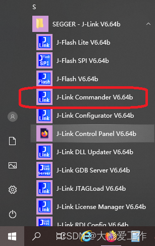
我们可以在开始菜单打开Jlinkcmd;
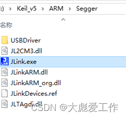
也可以在安装目录中打开Jlinkcmd;
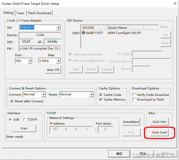
还可以在KEIL软件中debug窗口中打开;
建立连接

1.输入connect建立连接;
2.输入芯片型号,直接回车可以选择默认选项;
3.根据实际情况选择JTAG或者SWD;
4.设置下载速度,直接回车可以选择默认选项;
正确的连接目标芯片后:
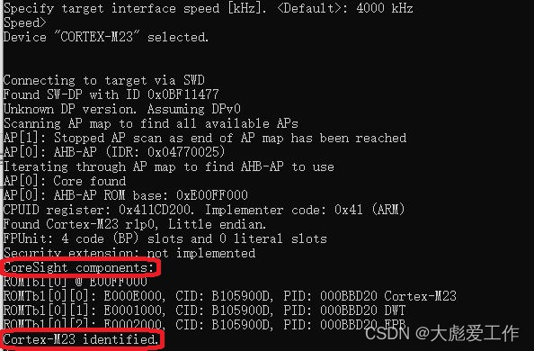
识别到内核,并通知“已识别”。
常用指令
Mem 读内存
mem8 读8比特内存
mem16 读16比特内存
mem32 读32比特内存
w1 写8比特内存
w2 写16比特内存
w4 写32比特内存
h 停止cpu运行的程序
setbp 设置断点
g 跳到代码段地址执行
s 单步执行(调试用)
r 复位
q 退出
实测举例
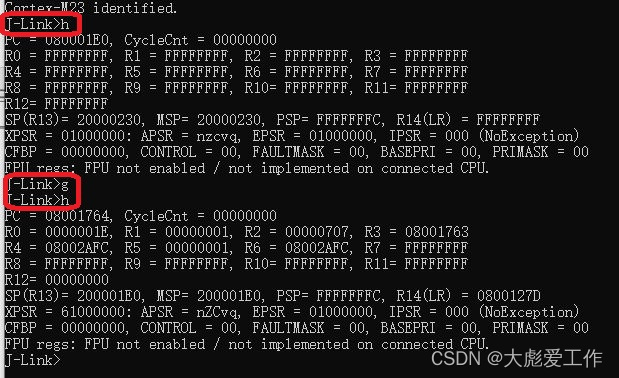
由以上指令运行结果可简单看出,PC初始值为0x080001E0,运行结束后指向0x08001764;

由以上指令运行结果可简单看出,地址0x00000004存储的值为:0x080001E1,地址0x08000004存储的值为:0x080001E1
指令大全
| Command (long) | Command (short) | Explanation |
| Basic | ||
| ? | Show information about all or specific commands | |
| Exit | Close J-Link connection and quit | |
| EoE | Exit on error | |
| Sleep | Waits the given time (in milliseconds) | |
| Log | Enables log to file | |
| ExpDevList | Export device names from DLL internal device list to text file | |
| ExpDevListXML | Export device names from DLL internal device list to XML file | |
| Configuration - J-Link | ||
| USB | Connect to J-Link via USB | |
| IP | Connect to J-Link via TCP/IP or to Remote Server | |
| SelPrb | Show list of all connected probes via specified interface. The Probe to communicate with can then be selected | |
| ShowEmuList | Show list of all connected probes via specified interface | |
| Power | Switch power supply for target (5V-Supply pin) on or off | |
| VTREF | Set fixed value for VTref on J-Link | |
| VCOM | Enable/disable VCOM Takes effect after power cycle of the probe | |
| Reboot | Reboots the connected probe. | |
| F | Show firmware info | |
| St | Show hardware status | |
| License | Show list of all available license commands | |
| IPAddr | Show/Assign IP address and subnetmask of/to connected Probe | |
| GWAddr | Show/Assign network gateway address of/to connected Probe | |
| DNSAddr | Show/Assign network DNS server address of/to connected Probe | |
| Conf | Show configuration of the connected Probe | |
| Calib | Calibrate the target current measurement | |
| Configuration - Target (CPU) | ||
| Con | Connect to target device | |
| Device | Select specific device J-Link shall connect to | |
| SI | Select target interface | |
| Speed | Set target interface speed | |
| LE | Change mode to little endian | |
| BE | Change mode to big endian | |
| Debugging | ||
| H | Halt CPU | |
| IH | Return current CPU state | |
| WH | Wait until CPU is halted or timeout is reached | |
| G | Start CPU if halted | |
| R | Reset CPU | |
| RX | Reset CPU with delay after reset | |
| Rst | Set the current reset type | |
| S | Execute step(s) on the CPU | |
| IS | Identify length of scan chain select register | |
| MS | Measure length of scan chain | |
| Regs | Display CPU register contents | |
| RReg | Read register | |
| WReg | Write register | |
| MoE | Shows mode-of-entry (CPU halt reason) | |
| SetBP | Set breakpoint | |
| ClrBP | Clear breakpoint | |
| SetWP | Set watchpoint | |
| ClrWP | Clear watchpoint | |
| VC | Write vector catch | |
| SetPC | Set the PC to specified value | |
| ReadAP | Read CoreSight AP register | |
| WriteAP | Write CoreSight AP register | |
| ReadDP | Read CoreSight DP register | |
| WriteDP | Write CoreSight DP register | |
| RCE | Read CP15 register | |
| WCE | Write CP15 register | |
| Term | Visualize printf output using DCC (SEGGER DCC handler running on target) | |
| Debugging - Memory operation | ||
| Mem | Read memory and show corresponding ASCII values | |
| Mem8 | Read 8-bit items | |
| Mem16 | Read 16-bit items | |
| Mem32 | Read 32-bit items | |
| W1 | Write 8-bit items | |
| W2 | Write 16-bit items | |
| W4 | Write 32-bit items | |
| Debugging - JTAG related | ||
| JTAGConf | Set number of IR/DR bits before Target device | |
| I | Read JTAG Id | |
| WJIR | Write JTAG command (IR) | |
| WJDR | Write JTAG data (DR) | |
| WJR | Write Raw JTAG data | |
| RTAP | Reset TAP Controller using state machine (111110) | |
| RT | Reset TAP Controller using nTRST | |
| Debugging - ICE | ||
| ICE | Show state of the embedded ICE macrocell (ICE breaker) | |
| RI | Read Ice register | |
| WI | Write Ice register | |
| TRACE | ||
| TC | Clear TRACE buffer | |
| TSS | Set TRACE size of trace buffer | |
| TSF | Set TRACE Format | |
| TSR | Show TRACE Regions (and analyze trace buffer) | |
| TStart | Start TRACE | |
| TStop | Stop TRACE | |
| SWO | ||
| SWOSpeed | Show supported SWO speeds | |
| SWOStart | Start SWO | |
| SWOStop | Stop SWO | |
| SWOStat | Display SWO status | |
| SWORead | Read and display SWO data | |
| SWOShow | Read and analyze SWO data | |
| SWOFlush | Flush SWO data | |
| SWOView | View SWO terminal data | |
| Flash programming | ||
| Erase | Erase flash (range) of selected device | |
| LoadFile | Load data file into target memory | |
| SaveBin | Save target memory range into binary file | |
| VerifyBin | Verfy if specified bin file is at the specified target memory location | |
| Flasher File I/O Commands | ||
| FWr | (Flasher only) Write file to probe | |
| FRd | (Flasher only) Read file from probe | |
| FShow | (Flasher only) Read and display file from probe | |
| FDel | (Flasher only) Delete file on probe | |
| FSz | (Flasher only) Display size of file on probe | |
| FList | (Flasher only) List directory on probe | |
| SecureArea | (Flasher only) Creates/Removes secure area on probe | |
| Measurement and test commands | ||
| PowerTrace | Perform power trace (not supported by all models) | |
| TestW | Measure download speed into target memory | |
| TestR | Measure upload speed from target memory | |
| TestC | Measure CPU speed | |
| TestNW | Measure network download speed | |
| TestNR | Measure network upload speed | |
| MR | Measure RTCK react time | |
| J-Link Pin control | ||
| C | Output clock(s) on the TCK pin | |
| C00 | Output clock(s) on the TCK pin, with TDI == 0 and TMS == 0 | |
| TCK0 | Clear TCK pin | |
| TCK1 | Set TCK pin | |
| TDI0 | Clear TDI pin | |
| TDI1 | Set TDI pin | |
| TMS0 | Clear TMS pin | |
| TMS1 | Set TMS pin | |
| TRST0 | Clear TRST pin | |
| TRST1 | Set TRST pin | |
| R0 | Clear RESET pin | |
| R1 | Set RESET pin | |


