- 1win11重置系统之后恢复自己的office服务_win11退回win10后office还在吗
- 2每天学python-盛最多水的容器_盛最多水的容器python
- 3API等级和Android版本对应关系以及历史_api19
- 4pytorch简单新型模型测试参数
- 5Centos7.9 安装配置mysql8.0.33_centos7.9 使用yum安装mysql 8并配置大小写不敏感
- 6scratch编程我的世界3D史蒂夫_用scratch做3d沙盒游戏代码
- 7每日五道java面试题之spring篇(三)
- 8Unity结合HTC Vive开发之射线与UI交互_unity vrtk 射线不显示但是可以点击ui怎么回事
- 9异常详细信息: System.InvalidCastException: 对象不能从 DBNull 转换为其他类型。_+ asbytearray “list2[0].asbytearray”引发了类型“system.i
- 10【JavaEE】idea的smart tomcat插件
【S32DS RTD实战】-1.4-基于S32K3创建配置FreeRTOS工程-控制GPIO点亮LED_sw32k3_freertos
赞
踩
目录(附DEMO,可下载,讲解过程超详细)
【S32K3_MCAL从入门到精通】合集:
S32K3_MCAL从入门到精通![]() https://blog.csdn.net/qfmzhu/category_12519033.html
https://blog.csdn.net/qfmzhu/category_12519033.html
1 下载FREERTOS RTD
打开链接S32K汽车通用MCU | NXP 半导体,网页往下翻,找到“软件”这一栏中的S32K3 Reference Software,单击其右侧的下载。

图1-1
在弹出的网页中,选择Automotive SW - S32K3 - FreeRTOS;
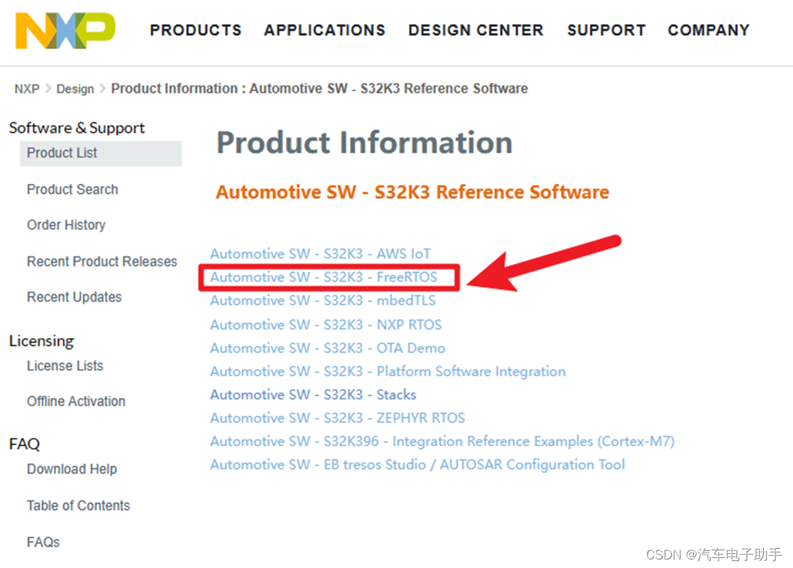
图1-2
在刷新的网页中,选择SW32K3_FreeRTOS_10.5.1_3.1.0_D2304;
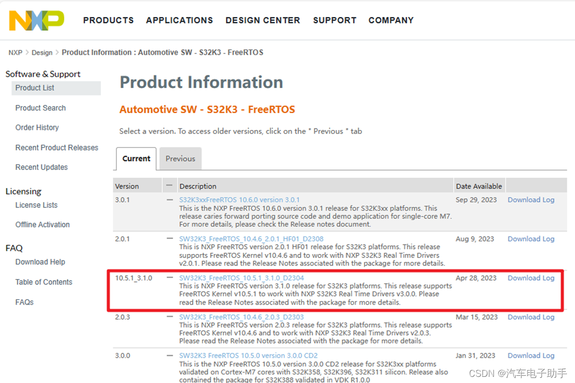
图1-3
在刷新的网页中,单击SW32K3_FreeRTOS_10_5_1_UOS_3_1_0_DS_updatesite_D2304.zip,下载该RTD。

图1-4
1.1 安装FREERTOS RTD
参考博文【S32K3环境搭建】-0.3-S32DS安装实时驱动RTD(Real-Time Driver)![]() https://blog.csdn.net/qfmzhu/article/details/134843314的第2.2章节,安装FreeRTOS RTD:SW32K3_FreeRTOS_10_5_1_UOS_3_1_0_DS_updatesite_D2304.zip。
https://blog.csdn.net/qfmzhu/article/details/134843314的第2.2章节,安装FreeRTOS RTD:SW32K3_FreeRTOS_10_5_1_UOS_3_1_0_DS_updatesite_D2304.zip。
FreeRTOS RTD(Real-Time Driver)安装后的效果:在S32DS Extensions and Updates中,你会看到安装好的FreeRTOS RTD。
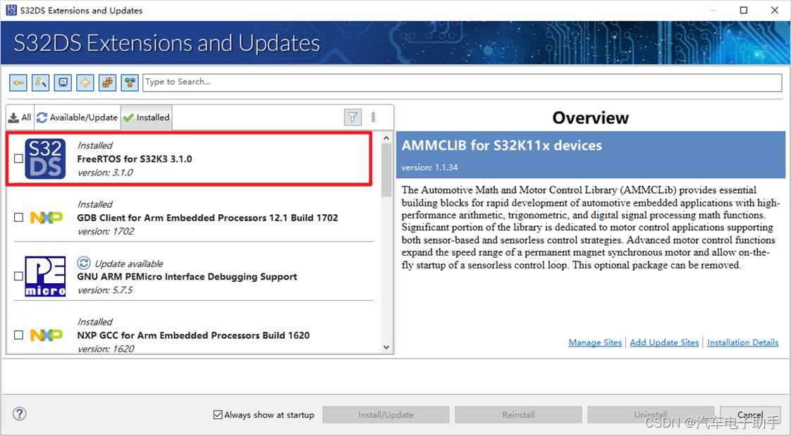
图1-5
2 确认S32DS已安装的AUTOSAR RTD
S32K3 RTD AUTOSAR R21-11 Version 3.0.0
S32K3xx RTD AUTOSAR R21-11 Version 3.0.0
S32K3xx development package V3.5.8

图2-1
3 基于S32K3创建&配置FREERTOS工程
在S32DS的Project Explorer中,鼠标右键,在其上下文中依次选择:New -- > S32DS Project from Example;
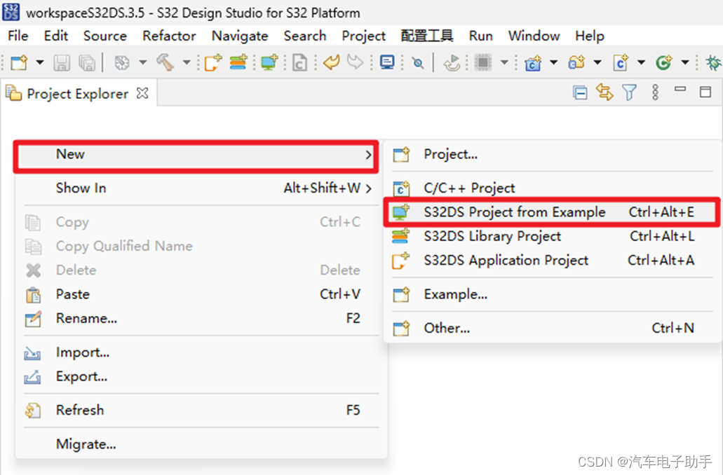
图3-1
在弹出的Create S32DS Project from Example对话框中,根据自己当前使用的MCU芯片型号进行选择,这里以FreeRTOS_Toggle_Led_Example_S32K312为例,单击Finish。

图3-2
注意Description中,关于该DEMO的介绍,其中包含了一些重要信息:
- (c) Copyright 2022-2023 NXP
-
- NXP Confidential. This software is owned or controlled by NXP and may only be used strictly
- in accordance with the applicable license terms. By expressly accepting
- such terms or by downloading, installing, activating and/or otherwise using
- the software, you are agreeing that you have read, and that you agree to
- comply with and are bound by, such license terms. If you do not agree to
- be bound by the applicable license terms, then you may not retain,
- install, activate or otherwise use the software.
-
- This file contains sample code only. It is not part of the production code deliverables.
- ========================================================================
-
- 1. Example Description
- Led D79-(Motherboard) - toggled using Clock, Siul2_Dio, Siul2_Port drivers and FreeRTOS.
- 1.1 The application software functionality
- The application uses 2 tasks SendTask and ReceiveTask. If ReceiveTask receives exactly Semaphore sent by SendTask, it will change led status.
- The application uses Siul2_Port_Ip_Init to initialize the pins and Clock_Ip_Init to initialize the clock sources.
-
- 2. Installation steps
- 2.1 Hardware installation
- 2.1.1 Supported boards
- - XS32K3X2CVB-Q172 PCB 48307 RevX1 SCH RevA (Daughter card)
- - X-S32K3XXX-MB PCB 47386 RevA SCH RevA (Motherboard)
- - S32K312EVB-Q172 50892 PCB RevA SCH RevB (EVB board)
- 2.1.2 Connections
- A wire connection is required between the following:
- - pin J290.4 (PTA_1 - gpio LED blink) to pin J290.3 (Led D79)-(Motherboard).
- - PTA29 is controlling the LED_RED in S32K312EVB-Q172 EVB board - when HIGH LED is ON when LOW LED is OFF.
- 2.1.3 Debugger
- The Pemicro must be connected to J32 10-pin JTAG Cortex Debug connector.
- 2.2 Software installation
- 2.2.1 Importing the S32 Design Studio project
- After opening S32 Design Studio, go to "File -> New -> S32DS Project From Example" and select this example. Then click on "Finish".
- The project should now be copied into your current workspace.
-
- 3. Generating, building and running the example application
- 3.1 Generating the S32 configuration
- Before running the example a configuration needs to be generated. First go to Project Explorer View in S32 DS and select the current project.
- Select the "S32 Configuration Tool" menu then click on the desired configuration tool (Pins, Cocks, Peripherals etc...).
- Clicking on any one of those will generate all the components. Make the desired changes(if any) then click on the "S32 Configuration Tool->Update Code" button.
- 3.2 Compiling the application
- Select the configuration to be built: RAM (Debug_RAM), or FLASH (Debug_FLASH) by left clicking on the downward arrow corresponding to the build button in eclipse.
- Wait for the build action to be completed before continuing to the next step. Check the compiler console for error messages; upon completion, the *.elf binary file
- should be created.
- 3.3 Running the application on the board
- 3.3.1 Running with P&E micro
- Go to Run and select Debug Configurations. There will be a debug configuration for this project:
-
- Configuration Name Description
- ------------------------------- -----------------------
- $(example)_Debug_FLASH_PNE Debug the FLASH configuration using PEMicro Debugging
- $(example)_Debug_RAM_PNE Debug the RAM configuration using PEMicro Debugging
-
- Select the desired debug configuration and click on Debug. Now the perspective will change to the Debug Perspective.
- Use the controls to control the program flow.
- 3.3.2 Running with Lauterbach
- To execute the example application load the executable file to the evaluation board using the Lauterbach debugger and the debug_t32/run.cmm script.
- Open debug_t32/run.cmm file in text editor if want to change target memory please change the values of &load_to and &elf_file.
- Run this script using T32 Lauterbach debugger after making the changes.
-

在Project Explorer中显示了S32K312的FREERTOS工程的文件结构,这里显然缺失了很多,下面我们一一配置。

图3-3
3.1 选择SDKs
在S32DS的Project Explorer中,选中工程名称FreeRTOS_Toggle_Led_Example_S32K312,鼠标右键,在其上下文中依次选择Properties;

图3-4
在弹出的Properties对话框中,选择SDKs后,选择Restore;

图3-5
PlatformSDK_S32K3_2022_03_S32K312_M7对应AUTOSAR版本:S32K3 Real-Time Drivers Version 2.0.3;
PlatformSDK_S32K3_S32K312_M7对应AUTOSAR版本:S32K3 RTD AUTOSAR R21-11 Version 3.0.0;
“加号”所在位置,表示该工程目前使用AUTOSAR RTD。这里我们默认高版本的V3.0.0,单击Apply and Close;

图3-6
在Project Explorer中,工程FreeRTOS_Toggle_Led_Example_S32K312,多了RTD,board和generate文件夹。

图3-7
3.2 增加FreeRTOS模块
双击mex文件,或者单击工具栏中的Open S32 Configuration Tools;

图3-8
在外设中,查看OS层中,是否已经添加了FreeRTOS模块。

图3-9
3.3 修改MCU芯片封装
在Pins引脚中,根据实际使用MCU封装情况,切换封装。

图3-10

图3-11
3.4 配置GPIO
在该FreeRTOS工程中,默认将PTA1和PTA29配置成了输出,详见图3-2中的Description。可根据您的PCB/开发板实际情况,在Pins引脚中,进行调整和适配。我们这里将其调整为PTB9和PTB10。
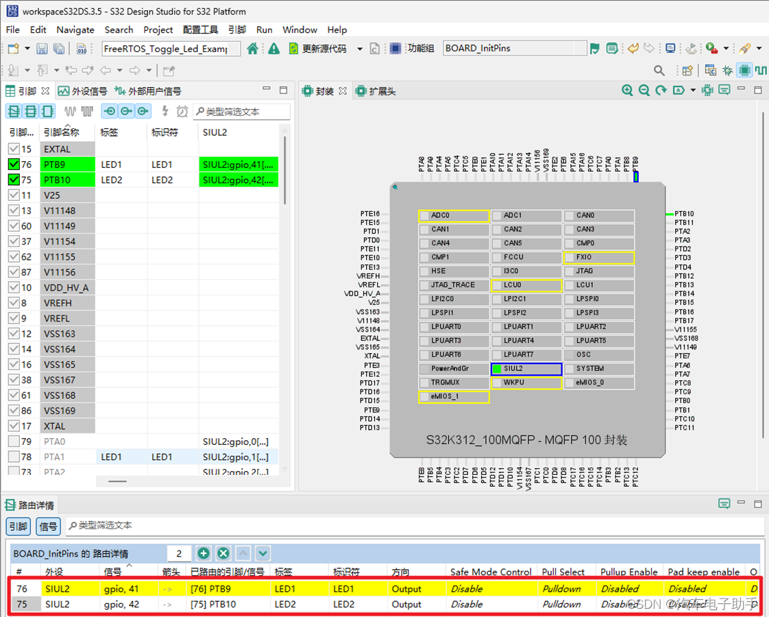
图3-12
3.5 修改HSE CLK时钟
在Clocks的时钟显示图中,修改HSE CLK的分频器,将其从120MHz修改为60MHz。

图3-12
3.5 更新代码
配置完成后,单击工具栏中更新代码,将配置生成代码。

图3-13
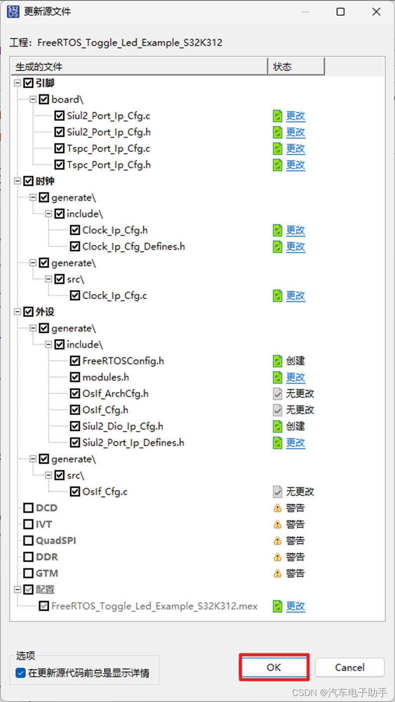
图3-14
配置完成后,在Project Explorer中,显示了FreeRTOS_Toggle_Led_Example_S32K312工程完整的结构。
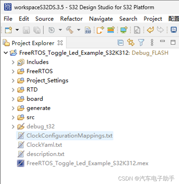
图3-15
4 main函数解读
在main函数中,使用xTaskCreate创建了两个Task: SendTask和ReceiveTask。在ReceiveTask函数中间隔Siul2_Dio_Ip_TogglePins周期拉高拉低PTB9和PTB10。
-
- /* Including necessary configuration files. */
- #include "Clock_Ip.h"
- #include "FreeRTOS.h"
- #include "task.h"
- #include "semphr.h"
- #include "Siul2_Port_Ip.h"
- #include "Siul2_Dio_Ip.h"
-
- #define main_TASK_PRIORITY ( tskIDLE_PRIORITY + 2 )
-
- SemaphoreHandle_t sem_handle;
- volatile BaseType_t testResult = 0x33U;
-
- /**
- * @brief SendTask is used to give the semaphore
- * @details SendTask give the semaphore every 1 second
- */
- void SendTask( void *pvParameters )
- {
- (void)pvParameters;
- BaseType_t operation_status;
-
- for( ;; )
- {
- operation_status = xSemaphoreGive(sem_handle);
- configASSERT(operation_status == pdPASS);
- /* Not very exciting - just delay... */
- vTaskDelay(pdMS_TO_TICKS(1000));
- }
- }
-
- /**
- * @brief ReceiveTask get the semaphore and toggle pins
- * @details ReceiveTask try to get the semaphore with portMAX_DELAY timeout,
- * After receiving the semaphore successfully, the led will be toggle
- * LED1_PIN <-> PTA1
- * LED2_PIN <-> PTA29
- */
- void ReceiveTask( void *pvParameters )
- {
- (void)pvParameters;
- BaseType_t operation_status;
- BaseType_t count = 0;
-
- for( ;; )
- {
- operation_status = xSemaphoreTake(sem_handle, portMAX_DELAY);
- configASSERT(operation_status == pdPASS);
- Siul2_Dio_Ip_TogglePins(LED1_PORT, (1 << LED1_PIN));
- Siul2_Dio_Ip_TogglePins(LED2_PORT, (1 << LED2_PIN));
- if(count++ > 10)
- {
- testResult = 0x5AU;
- }
- }
- }
-
- /**
- * @brief Main function of the example
- * @details Initializes the used drivers and uses 1 binary Semaphore and
- * 2 tasks to toggle a LED.
- */
- int main(void)
- {
- /* Initialize Clock */
- Clock_Ip_StatusType Status_Init_Clock = CLOCK_IP_ERROR;
- Status_Init_Clock = Clock_Ip_Init(Clock_Ip_aClockConfig);
-
- if (Status_Init_Clock != CLOCK_IP_SUCCESS)
- {
- while(1); /* Error during initialization. */
- }
-
- /* Initialize all pins using the Port driver */
- Siul2_Port_Ip_PortStatusType Status_Init_Port = SIUL2_PORT_ERROR;
- Status_Init_Port = Siul2_Port_Ip_Init(NUM_OF_CONFIGURED_PINS0, g_pin_mux_InitConfigArr0);
-
- if(Status_Init_Port != SIUL2_PORT_SUCCESS)
- {
- while(1); /* Error during initialization. */
- }
-
- vSemaphoreCreateBinary(sem_handle);
- xTaskCreate( SendTask , ( const char * const ) "SendTask", configMINIMAL_STACK_SIZE, (void*)0, main_TASK_PRIORITY, NULL );
- xTaskCreate( ReceiveTask, ( const char * const ) "RecTask" , configMINIMAL_STACK_SIZE, (void*)0, main_TASK_PRIORITY + 1, NULL );
- vTaskStartScheduler();
-
- for( ;; );
-
- return 0;
- }

5 附:FreeRTOS DEMO
该博文,附上了配置好的FreeRTOS DEMO下载链接。
结尾
获取更多“汽车电子资讯”和“工具链使用”,
请关注CSDN博客“汽车电子助手”,做您的好助手。


