- 1想开发一个纯血鸿蒙版APP,需要掌握哪些技能?,基于HarmonyOS鸿蒙的app的设计与开发_鸿蒙app技术点
- 2大话常用限流算法与应用场景_限流算法优缺点
- 3人工智能GIS技术升级,将应用到更多领域_人工智能的兴起和发展对gis产生的影响
- 4NOIP2018 普及组复赛题解_noip2018复赛试题下载
- 5ESP32s3与Lsm6ds3通信---i2c【开源】
- 6Python课设——豆瓣top250
- 7开发者应警惕的七种糟糕职业规划错误
- 8图解PHP & MySQL:轻松掌握服务器端Web开发
- 9vivado 创建和运行链路清扫_vivado phase5 sweep
- 10idea 将项目上传到gitee远程仓库具体操作_idea上传到gitee远程仓库
基于ENSP的高校网络规划_某大学校园网络建设方案设计及仿真 论文ensp
赞
踩
项目概况
一、需求描述
某新建校以光纤连接了全校近70栋楼宇。共布有2万多个有线网络端口。总体设计如下:
1、办公楼宇区域实现网络高可靠性设计,接入层交换机断掉任何一根链路,汇聚或核心交换机Down条任何一台设备,都不影响数据的正常转发;
2、总部服务器区和临潼分校同理;
3、汉中分校人数较少,所以使用单臂路由实现内网互通;
4、要求西安总校,临潼分校,汉中分校内网用户都能访问互联网;
5、要求公网用户能够访问西安总校服务器区域的HTTP Server和FTP Server;
6、要求西安总校和临潼汉中分校之间通过DSVPN能够实现内网互通。
二、实验拓扑
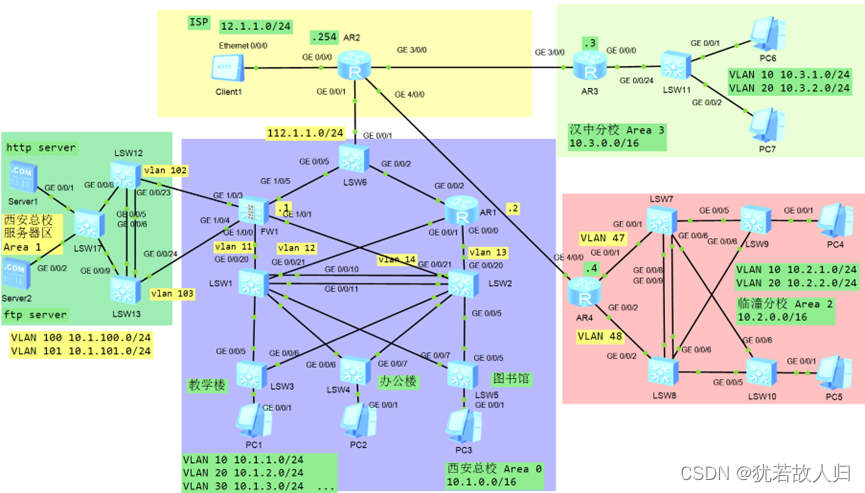
三、配置过程
<一>西安总校配置
-
创建VLAN,加接口
PC1属于VLAN10,网段属于10.1.1.0/24网段。
PC2属于VLAN10,网段属于10.1.2.0/24网段。
PC3属于VLAN10,网段属于10.1.3.0/24网段。
由上拓扑图可知,在西安总校的办公区域划分多个vlan,此拓扑西安总校办公区域中客户端所在的vlan区域分别为vlan10、20、30、40,与之对应的网段分别为:10.1.1.0/24、10.1.2.0/24、10.1.3.0/24、10.1.4.0/24。在SW1和SW2上分别创建vlan 11、12、13、14。交换机与终端连接的线路使用access链路,交换机互连的路线使用Trunk。同时将SW1和SW2之间的链路捆绑为e-trunk,做备份链路,链路类型为Trunk,允许所有的vlan通过。接入层交换机为SW3、SW4、SW5,上行交换机为SW1、SW2,可知在此处做冗余备份,以确保两台核心交换机任何一个故障时链路整体连通性仍旧畅通。
配置命令如下:
SW1上:
| [SW1]v b 10 20 30 40 11 12 [SW1]int g0/0/5 [SW1-GigabitEthernet0/0/5]p l t [SW1-GigabitEthernet0/0/5]p t a v a [SW1-GigabitEthernet0/0/5]int g0/0/6 [SW1-GigabitEthernet0/0/6]p l t [SW1-GigabitEthernet0/0/6]p t a v a [SW1-GigabitEthernet0/0/6]int g0/0/7 [SW1-GigabitEthernet0/0/7]p l t [SW1-GigabitEthernet0/0/7]p t a v a [SW1-GigabitEthernet0/0/7]int g0/0/20 [SW1-GigabitEthernet0/0/20]p l a [SW1-GigabitEthernet0/0/20]p d v 11 [SW1-GigabitEthernet0/0/20]int g0/0/21 [SW1-GigabitEthernet0/0/21]p l a [SW1-GigabitEthernet0/0/21] p d v 12 [SW1-GigabitEthernet0/0/21]q [SW1]int Eth-Trunk 1 [SW1-Eth-Trunk1]trunkport GigabitEthernet 0/0/10 to 0/0/ [SW1-Eth-Trunk1]p l t [SW1-Eth-Trunk1]p t a v a [SW1-Eth-Trunk1]q |
SW2上:
| [SW2]v b 10 20 30 40 13 14 [SW2]int g0/0/5 [SW2-GigabitEthernet0/0/5]p l t [SW2-GigabitEthernet0/0/5]p t a v a [SW2-GigabitEthernet0/0/5]int g0/0/6 [SW2-GigabitEthernet0/0/6]p l t [SW2-GigabitEthernet0/0/6]p t a v a [SW2-GigabitEthernet0/0/6]int g0/0/7 [SW2-GigabitEthernet0/0/7]p l t [SW2-GigabitEthernet0/0/7]p t a v a [SW2-GigabitEthernet0/0/7]int g0/0/20 [SW2-GigabitEthernet0/0/20]p l a [SW2-GigabitEthernet0/0/20]p d v 13 [SW2-GigabitEthernet0/0/20]int g0/0/21 [SW2-GigabitEthernet0/0/21]p l a [SW2-GigabitEthernet0/0/21]p d v 14 [SW2-GigabitEthernet0/0/21]q [SW2]int Eth-Trunk 1 [SW2-Eth-Trunk1]trunkport GigabitEthernet 0/0/10 to 0/0/11 [SW2-Eth-Trunk1]p l t [SW2-Eth-Trunk1]p t a v a |
SW3上:
| [SW3]v b 10 20 30 40 //创建vlan [SW3]int g0/0/1 [SW3-GigabitEthernet0/0/1] p l a [SW3-GigabitEthernet0/0/1]p d v 10 [SW3-GigabitEthernet0/0/1]int g0/0/5 [SW3-GigabitEthernet0/0/5]p l t [SW3-GigabitEthernet0/0/5]p t a v a [SW3-GigabitEthernet0/0/5]int g0/0/6 [SW3-GigabitEthernet0/0/6]p l t [SW3-GigabitEthernet0/0/6]p t a v a |
SW4上:
| [SW4]v b 10 20 30 40 [SW4]int g0/0/1 [SW4-GigabitEthernet0/0/1]p l a [SW4-GigabitEthernet0/0/1]p d v 20 [SW4-GigabitEthernet0/0/1]int g0/0/6 [SW4-GigabitEthernet0/0/6]p l t [SW4-GigabitEthernet0/0/6]p t a v a [SW4-GigabitEthernet0/0/6]int g0/0/7 [SW4-GigabitEthernet0/0/7]p l t [SW4-GigabitEthernet0/0/7]p t a v a |
SW5上:
| [SW5]v b 10 20 30 40 [SW5]int g0/0/1 [SW5-GigabitEthernet0/0/1]p l a [SW5-GigabitEthernet0/0/1]p d v 30 [SW5-GigabitEthernet0/0/1]int g0/0/5 [SW5-GigabitEthernet0/0/5]p l t [SW5-GigabitEthernet0/0/5]p t a v a [SW5-GigabitEthernet0/0/5]int g0/0/7 [SW5-GigabitEthernet0/0/7]p l t [SW5-GigabitEthernet0/0/7]p t a v a |
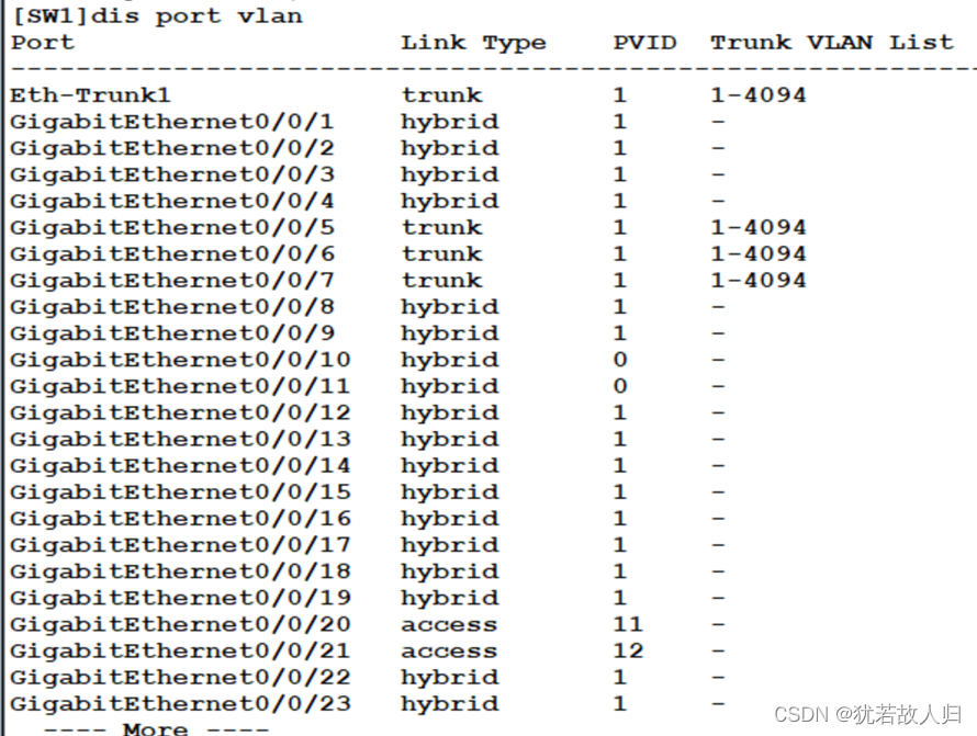
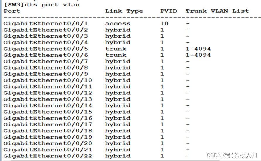
由上可知基本的vlan已经划分完成,下面检验查看是否有误(以SW1和SW3为例):
SW1上:
SW3上:
-
配置MSTP—破环
要求SW1成为VLAN10 20的根桥,VLAN30 40的次根,SW2成为VLAN 30 40的根桥,VLAN1020的次根。将连接接终端的接口配置为边缘端口。region-name SLG-group1x,x代表组编号。
在SW3和SW5上分别使用display stp region-configuration, display stp brief截图展示。相关配置命令如下:
SW1(SW2、3、4、5上相同):
| [SW1]stp region-configuration [SW1-mst-region]region-name SLG-group113 //命名为SLG-group1+13(组号13) [SW1-mst-region]revision-level 1 //修订级别 [SW1-mst-region]instance 1 vlan 10 20 [SW1-mst-region]instance 2 vlan 30 40 [SW1-mst-region]active region-configuration //激活region [SW1-mst-region]dis th # stp region-configuration region-name SLG-group113 revision-level 1 instance 1 vlan 10 20 instance 2 vlan 30 40 active region-configuration # return |
因为要使得SW1成为VLAN 10 20的根桥,VLAN30 40的次根;SW2成为VLAN 30 40的根桥,VLAN1020的次根,所以下面将对二者上的instance的优先级进行更改(优先级越小越优先,默认为32768):
SW1上:
| SW1]stp instance 1 priority 0 [SW1]stp instance 2 priority 4096 |
SW2上:
| [SW2] stp instance 2 priority 0 [SW2]stp instance 1 priority 4096 |
下面将对配置的结果进行查看:


由上图可知,已经将vlan10 20 划分到instance1 中,vlan 30 40 划分到instance2中。且查看Stp的接口状态可知,在SW3上,SW1为根桥时,在instance 1中5是根端口,6是阻塞口,处于丢弃状态;SW2为根桥时,5口是阻塞口处于丢弃状态,6口为根端口。在SW5上同理。
-
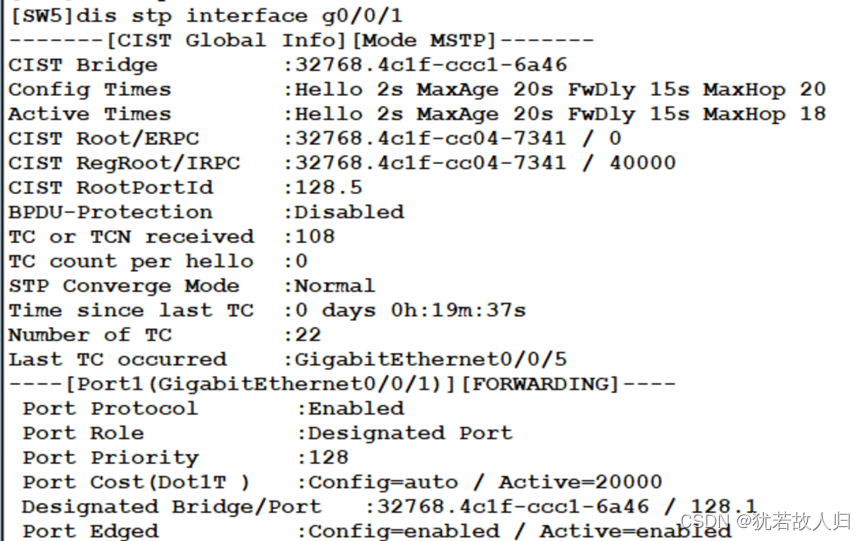
配置边缘接口
下面将连接终端的接口配置成为边缘接口,配置命令如下:
SW3上:
| [SW3]int g0/0/1 [SW3-GigabitEthernet0/0/1]stp edged-port en |
SW4上:
| [SW4]int g0/0/1 [SW4-GigabitEthernet0/0/1]stp edged-port enable |
SW5上:
| [SW5]int g0/0/1 [SW5-GigabitEthernet0/0/1]stp edged-port enable |
未曾配置之前:

配置完成之后:
-
配置VLAN间路由
利用SW1和SW2作为汇聚和核心的交换机,为了实现vlan间路由,为vlanif配置网关。
SW1上:
| [SW1]int vlan10 [SW1-Vlanif10]ip add 10.1.1.1 24 [SW1-Vlanif10]q [SW1]int vlan20 [SW1-Vlanif20]ip add 10.1.2.1 24 [SW1-Vlanif20]q [SW1]int vlan30 [SW1-Vlanif30]ip add 10.1.3.1 24 [SW1-Vlanif30]q [SW1] int vlan40 [SW1-Vlanif40]ip add 10.1.4.1 24 |
SW2上:
| [SW2]int vlan10 [SW2-Vlanif10]ip add 10.1.1.2 24 [SW2-Vlanif10]int vlan20 [SW2-Vlanif20]ip add 10.1.2.2 24 [SW2-Vlanif20]int vlan30 [SW2-Vlanif30]ip add 10.1.3.2 24 [SW2-Vlanif30]int vlan 40 [SW2-Vlanif40]ip add 10.1.4.2 24 [SW2-Vlanif40]q |
-
配置VRRP
此时可以将vlan10 20 的网关指向SW1,vlan 30 40的网关指向SW2 ,但是此操作下,若SW1或者SW2任意一个设备发生故障,则需手动更改网关,故我们利用VRRP将网关指向VRRP。让vlan10 20 30 40 分别虚拟一个.113 的IP,并将网关指向.113,并且让SW1成为vlan 10 20 的master,vlan 30 40 的backup;让SW2成为vlan 30 40 的master,vlan 10 20 的backup。此时,若SW1或者SW2发生故障,用户并不需要更改网关地址,会将backup上升成为master,从而使得链路依旧能够正常使用。以下为VRRP的相关配置:
SW1上:
| [SW1-Vlanif10]vrrp vrid 1 virtual-ip 10.1.1.113 //虚拟网关指向.113 [SW1-Vlanif10]vrrp vrid 1 priority 200 //优先级更改为200 [SW1-Vlanif10]vrrp vrid 1 preempt-mode timer delay 60 //抢占延时60秒 [SW1-Vlanif10]vrrp vrid 1 track interface GigabitEthernet 0/0/20 //上行链路接口 [SW1-Vlanif10]vrrp vrid 1 track interface GigabitEthernet 0/0/20 re [SW1-Vlanif10]vrrp vrid 1 track interface GigabitEthernet 0/0/20 reduced 120 //若上行接口down掉,优先级自动降低120,成为80,小于backup的优先级100,默认100,此时backup成为master [SW1-Vlanif10]dis th //查看配置情况 # interface Vlanif10 ip address 10.1.1.1 255.255.255.0 vrrp vrid 1 virtual-ip 10.1.1.113 vrrp vrid 1 priority 200 vrrp vrid 1 preempt-mode timer delay 60 vrrp vrid 1 track interface GigabitEthernet0/0/20 reduced 120 # Return /SW1作为vlan10 20的根桥,所以10 20的VRRP配置相似,30 40 的优先级等相关不做更改/ [SW1-Vlanif10]int vlan20 [SW1-Vlanif20]vrrp vrid 2 virtual-ip 10.1.2.113 [SW1-Vlanif20]vrrp vrid 2 priority 200 [SW1-Vlanif20]vrrp vrid 2 preempt-mode timer delay 60 [SW1-Vlanif20]vrrp vrid 2 track interface GigabitEthernet 0/0/20 reduced 120 [SW1-Vlanif20]dis th # interface Vlanif20 ip address 10.1.2.1 255.255.255.0 vrrp vrid 2 virtual-ip 10.1.2.113 vrrp vrid 2 priority 200 vrrp vrid 2 preempt-mode timer delay 60 vrrp vrid 2 track interface GigabitEthernet0/0/20 reduced 120 # return [SW1-Vlanif20]int vlan30 [SW1-Vlanif30]vrrp vrid 3 virtual-ip 10.1.3.113 [SW1-Vlanif30]dis th # interface Vlanif30 ip address 10.1.3.1 255.255.255.0 vrrp vrid 3 virtual-ip 10.1.3.113 # Return [SW1-Vlanif30]int vlan40 [SW1-Vlanif40]vrrp vrid 4 virtual-ip 10.1.4.113 [SW1-Vlanif40]dis th # interface Vlanif40 ip address 10.1.4.1 255.255.255.0 vrrp vrid 4 virtual-ip 10.1.4.113 # return |
SW2上与SW1上同理:
| [SW2]int vlan10 [SW2-Vlanif10]vrrp vrid 1 virtual-ip 10.1.1.113 [SW2-Vlanif10]int vlan20 [SW2-Vlanif20]vrrp vrid 2 virtual-ip 10.1.2.113 [SW2-Vlanif20]int vlan30 [SW2-Vlanif30]vrrp vrid 3 virtual-ip 10.1.3.113 [SW2-Vlanif30]vrrp vrid 3 preempt-mode timer delay 60 [SW2-Vlanif30]vrrp vrid 3 track interface GigabitEthernet 0/0/20 reduced 120 [SW2-Vlanif30]vrrp vrid 3 priority 200 [SW2-Vlanif30]dis th # interface Vlanif30 ip address 10.1.3.2 255.255.255.0 vrrp vrid 3 virtual-ip 10.1.3.113 vrrp vrid 3 priority 200 vrrp vrid 3 preempt-mode timer delay 60 vrrp vrid 3 track interface GigabitEthernet0/0/20 reduced 120 # return [SW2-Vlanif30]int vlan40 [SW2-Vlanif40]vrrp vrid 4 virtual-ip 10.1.4.113 [SW2-Vlanif40]vrrp vrid 4 priority 200 [SW2-Vlanif40]vrrp vrid 4 preempt-mode timer delay 60 [SW2-Vlanif40]vrrp vrid 4 track interface GigabitEthernet 0/0/20 reduced 120 [SW2-Vlanif40]dis th # interface Vlanif40 ip address 10.1.4.2 255.255.255.0 vrrp vrid 4 virtual-ip 10.1.4.113 vrrp vrid 4 priority 200 vrrp vrid 4 preempt-mode timer delay 60 vrrp vrid 4 track interface GigabitEthernet0/0/20 reduced 120 # return |
下面对SW1和SW2上的VRRP配置结果进行查看:
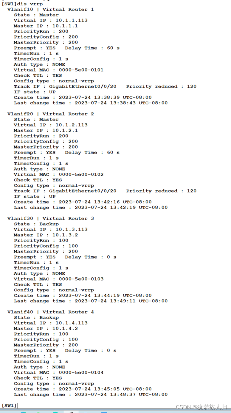
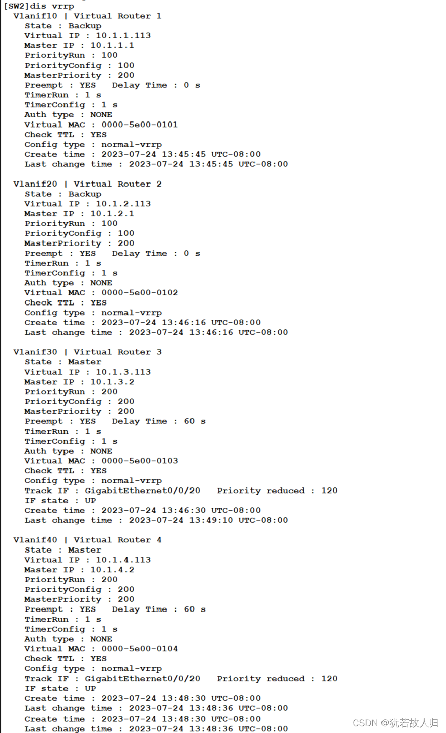
此时已经完成了vlan间路由和VRRP的配置,办公区域之间的终端可以互通,下面将进行连通性测试:
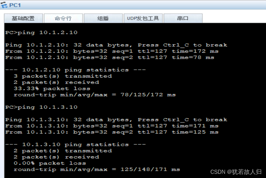
由图可知,连通性良好,即完成了内网之间的互通。
-
配置三层互联接口
由上可知,已经将西安分校的办公区域的内网打通,下面需要做交换机上的三层互连,由拓扑图,定义交换机与防火墙、路由器之间的网段为192.168.X.X网段,相应的IP地址规划如配置命令中所示:
SW1上:
| [SW1]int vlan11 [SW1-Vlanif11]ip add 192.168.11.254 24 [SW1-Vlanif11]int vlan12 [SW1-Vlanif12]ip add 192.168.12.254 24 [SW1-Vlanif12]q |
SW2上:
| [SW2]int vlan13 [SW2-Vlanif13]ip add 192.168.13.254 24 [SW2-Vlanif13]int vlan14 [SW2-Vlanif14]ip add 192.168.14.254 24 [SW2-Vlanif14]q |
-
配置防火墙
FW1上:
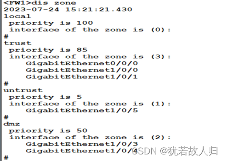
首先在防火墙上划区域,分接口,加IP:
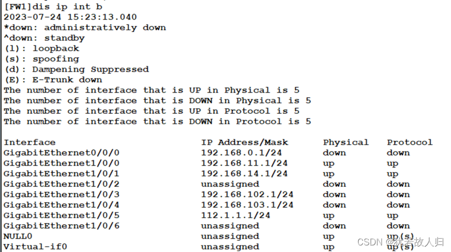
| [FW1]firewall zone trust [FW1-zone-trust]add interface GigabitEthernet 1/0/0 [FW1-zone-trust]add interface GigabitEthernet 1/0/1 [FW1-zone-trust]q [FW1]firewall zone untrust [FW1-zone-untrust]add interface GigabitEthernet 1/0/5 [FW1-zone-untrust]q [FW1]firewall zone dmz [FW1-zone-dmz]add interface GigabitEthernet 1/0/3 [FW1-zone-dmz]add interface GigabitEthernet 1/0/4 [FW1-zone-dmz]q [FW1]int g1/0/0 [FW1-GigabitEthernet1/0/0]ip add 192.168.11.1 24 [FW1-GigabitEthernet1/0/0]int g1/0/1 [FW1]int g1/0/1 [FW1-GigabitEthernet1/0/1]ip add 192.168.14.1 24 [FW1-GigabitEthernet1/0/1]int g1/0/3 [FW1-GigabitEthernet1/0/3]ip add 192.168.102.1 24 [FW1-GigabitEthernet1/0/3]int g1/0/4 [FW1-GigabitEthernet1/0/4]ip add 192.168.103.1 24 [FW1-GigabitEthernet1/0/4]int g1/0/5 [FW1-GigabitEthernet1/0/5]ip add 112.1.1.1 24 [FW1-GigabitEthernet1/0/5]q |
区域划分结果:
接口IP配置结果:
R1上:
| [R1]int g0/0/0 [R1-GigabitEthernet0/0/0]ip add 192.168.13.2 24 [R1-GigabitEthernet0/0/0]int g0/0/1 [R1-GigabitEthernet0/0/1]ip add 192.168.12.2 24 [R1-GigabitEthernet0/0/1]int g0/0/2 [R1-GigabitEthernet0/0/2]ip add 112.1.1.2 24 |
公网路由器R2:
| [R2-GigabitEthernet0/0/0]ip add 12.1.1.254 24 [R2-GigabitEthernet0/0/0]int g4/0/0 [R2-GigabitEthernet4/0/0]ip add 24.1.1.254 24 [R2-GigabitEthernet4/0/0]int g3/0/0 [R2-GigabitEthernet3/0/0]ip add 23.1.1.254 24 |
-
配置DMZ服务器区域VLAN,MSTP,VLAN间路由,互联三层IP;
创建相应的vlan并加上对应的接口:
SW17上:
| [SW17]v b 100 101 [SW17]int g0/0/1 [SW17-GigabitEthernet0/0/1]p l a [SW17-GigabitEthernet0/0/1]p d v 100 [SW17-GigabitEthernet0/0/1]int g0/0/2 [SW17-GigabitEthernet0/0/2]p l a [SW17-GigabitEthernet0/0/2]p d v 101 [SW17-GigabitEthernet0/0/2]int g [SW17-GigabitEthernet0/0/8]p l t [SW17-GigabitEthernet0/0/8]p t a v a [SW17-GigabitEthernet0/0/8]int g0/0/9 [SW17-GigabitEthernet0/0/9]p l t [SW17-GigabitEthernet0/0/9]p t a v a |
SW 12 上:
| [SW12]v b 100 101 102 [SW12]int g0/0/8 [SW12-GigabitEthernet0/0/8]p l t [SW12-GigabitEthernet0/0/8]p t a v a [SW12-GigabitEthernet0/0/23]p l a [SW12-GigabitEthernet0/0/23]p d v 102 [SW12]int Eth-Trunk 1 [SW12-Eth-Trunk1]trunkport GigabitEthernet 0/0/05 to 0/0/6 [SW12-Eth-Trunk1]p l t [SW12-Eth-Trunk1]p t a v a |
SW13上:
| [SW13]v b 100 101 103 [SW13]int g0/0/9 [SW13-GigabitEthernet0/0/9]p l t [SW13-GigabitEthernet0/0/9]p t a v a [SW13-GigabitEthernet0/0/9]int g0/0/24 [SW13-GigabitEthernet0/0/24]p l a [SW13-GigabitEthernet0/0/24]p d v 103 [SW13-GigabitEthernet0/0/24]q [SW13]int Eth-Trunk 1 [SW13-Eth-Trunk1]trunkport GigabitEthernet 0/0/5 to 0/0/6 [SW13-Eth-Trunk1]p l t [SW13-Eth-Trunk1]p t a v a |
-
配置MSTP
下面对MSTP进行配置,要求为vlan 100的根桥为SW12,vlan101 的根桥为SW13
SW17上(此配置SW12 SW13上相同):
| [SW17-mst-region]region-name SLG-group13 [SW17-mst-region]revision-level 1 [SW17-mst-region]instance 1 vlan 100 [SW17-mst-region]instance 2 vlan 101 [SW17-mst-region]active region-configuration |
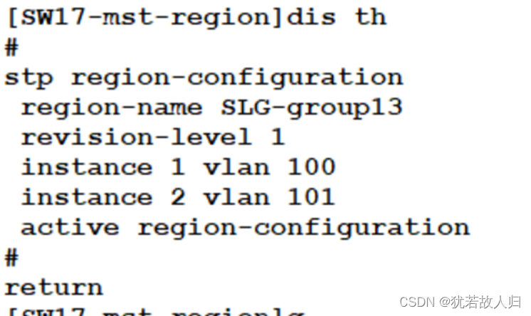
由于要使SW 12成为vlan 100的根桥,SW13成为vlan 101 的根桥,故在SW 12和SW 13上分别修改instance 1和instance 2的优先级:
SW12上:
| [SW12]stp instance 1 priority 0 [SW12]stp instance 2 priority 4096 |
SW13上:
| [SW13]stp instance 1 priority 4096 [SW13]stp instance 2 priority 0 |
在SW17上查看:


交换机与PC相连的端口配置成为边缘接口:
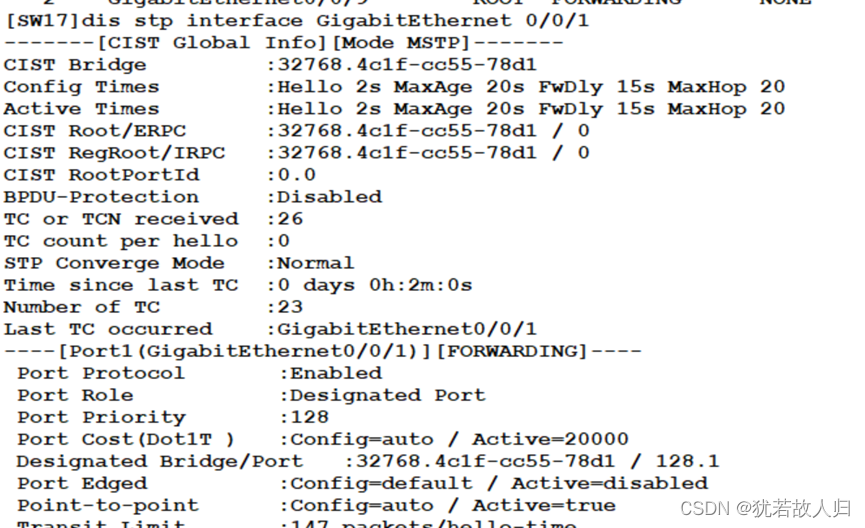
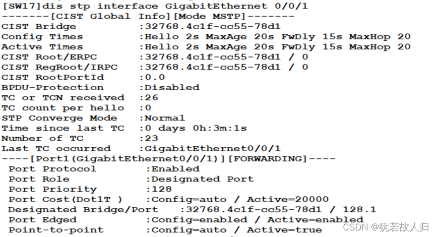
由于DMZ区域和vlan 100 以及 vlan 101之间需要通信,故使用三层交换机的vlanif接口实现vlan路由。下面配置vlan间路由:
SW12:
| [SW12]intn vlan 100 [SW12-Vlanif100]ip add 10.1.1.100.1 24 [SW12-Vlanif100]int vlan101 [SW12-Vlanif101]ip add 10.1.101.1 24 |
SW13上:
| [SW13]int vlan 100 [SW13-Vlanif100]ip add 10.1.100.2 24 [SW13-Vlanif100]int vlan 101 [SW13-Vlanif101]ip add 10.1.101.2 24 |
为了保证链路备份,需在dmz区域做VRRP:
SW12上:
| [SW12]int vlan 100 [SW12-Vlanif100]vrrp vrid 1 virtual-ip 10.1.100.113 [SW12-Vlanif100]vrrp vrid 1 priority 200 [SW12-Vlanif100]vrrp vrid 1 preempt-mode timer delay 60 [SW12-Vlanif100]vrrp vrid 1 track interface GigabitEthernet 0/0/23 reduced 120 [SW12-Vlanif100]dis th # interface Vlanif100 vrrp vrid 1 virtual-ip 10.1.100.113 vrrp vrid 1 priority 200 vrrp vrid 1 preempt-mode timer delay 60 vrrp vrid 1 track interface GigabitEthernet0/0/23 reduced 120 # return [SW12-Vlanif100]ip add 10.1.100.1 24 [SW12-Vlanif100]dis th # interface Vlanif100 ip address 10.1.100.1 255.255.255.0 vrrp vrid 1 virtual-ip 10.1.100.113 vrrp vrid 1 priority 200 vrrp vrid 1 preempt-mode timer delay 60 vrrp vrid 1 track interface GigabitEthernet0/0/23 reduced 120 # return [SW12-Vlanif100]int vlan 101 [SW12-Vlanif101]vrrp vrid 2 virtual-ip 10.1.101.113 [SW12-Vlanif101]dis th # interface Vlanif101 ip address 10.1.101.1 255.255.255.0 vrrp vrid 2 virtual-ip 10.1.101.113 # return |
SW13上:
| [SW13]int vlan 100 [SW13-Vlanif100]vrrp vrid 1 virtual-ip 10.1.100.113 [SW13-Vlanif100]int vlan 101 [SW13-Vlanif101]vrrp vrid 2 virtual-ip 10.1.101.113 [SW13-Vlanif101]vrrp vrid 2 preempt-mode timer delay 60 [SW13-Vlanif101]vrrp vrid 2 priority 200 [SW13-Vlanif101]vrrp vrid 2 track interface GigabitEthernet 0/0/24 reduced 120 |
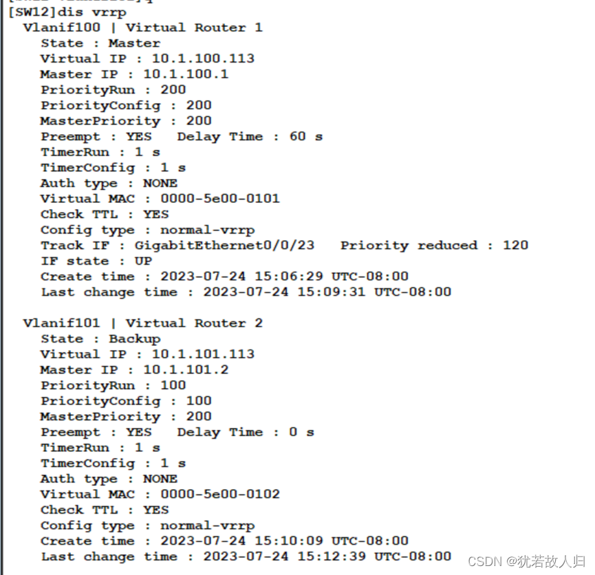

查看dmz区域的内部通信:

-
配置全网路由
由拓扑可知,将西安总校的办公区域放置在OSPF的area0 区域,服务器区放在area1区域。临潼校区放置在area2区域,汉中校区放置在area 3 区域。OSPF配置即将自己的直连网段宣告即可。
SW1上:
| [SW1]ospf 1 router-id 11.1.1.1 [SW1-ospf-1]area 0 [SW1-ospf-1-area-0.0.0.0]network 10.1.1.0 0.0.0.255 [SW1-ospf-1-area-0.0.0.0]network 10.1.2.0 0.0.0.255 [SW1-ospf-1-area-0.0.0.0]network 10.1.3.0 0.0.0.255 [SW1-ospf-1-area-0.0.0.0]network 10.1.4.0 0.0.0.255 [SW1-ospf-1-area-0.0.0.0]network 192.168.11.0 0.0.0.255 [SW1-ospf-1-area-0.0.0.0]network 192.168.12.0 0.0.0.255 [SW1-ospf-1-area-0.0.0.0]dis th # area 0.0.0.0 network 10.1.1.0 0.0.0.255 network 10.1.2.0 0.0.0.255 network 10.1.3.0 0.0.0.255 network 10.1.4.0 0.0.0.255 network 192.168.11.0 0.0.0.255 network 192.168.12.0 0.0.0.255 # return |
SW2上
| [SW2]ospf 1 router-id 22.1.1.1 [SW2-ospf-1]area 0 [SW2-ospf-1-area-0.0.0.0]network 10.1.1.0 0.0.0.255 [SW2-ospf-1-area-0.0.0.0]network 10.1.2.0 0.0.0.255 [SW2-ospf-1-area-0.0.0.0]network 10.1.3.0 0.0.0.255 [SW2-ospf-1-area-0.0.0.0]network 10.1.4.0 0.0.0.255 [SW2-ospf-1-area-0.0.0.0]network 192.168.13.0 0.0.0.255 [SW2-ospf-1-area-0.0.0.0]network 192.168.14.0 0.0.0.255 [SW2-ospf-1-area-0.0.0.0]dis th # area 0.0.0.0 network 10.1.1.0 0.0.0.255 network 10.1.2.0 0.0.0.255 network 10.1.3.0 0.0.0.255 network 10.1.4.0 0.0.0.255 network 192.168.13.0 0.0.0.255 network 192.168.14.0 0.0.0.255 # return |
FW1上:将0、1、3、4接口均宣告在area 0区域,使其成为DR,使SW12、SW13成为BDR:
| [FW1]ospf 1 router-id 111.1.1.1 [FW1-ospf-1]area 0t [FW1-ospf-1-area-0.0.0.0]network 192.168.11.0 0.0.0.255 [FW1-ospf-1-area-0.0.0.0]network 192.168.14.0 0.0.0.255 [FW1-ospf-1-area-0.0.0.0]network 192.168.102.0 0.0.0.255 [FW1-ospf-1-area-0.0.0.0]network 192.168.103.0 0.0.0.255 |
R1上:
|
[R1]ospf 1 router-id 112.1.1.1 [R1-ospf-1]area 0 [R1-ospf-1-area-0.0.0.0]net [R1-ospf-1-area-0.0.0.0]network 192.168.12.0 0.0.0.255 [R1-ospf-1-area-0.0.0.0]network 192.168.13.0 0.0.0.255 |
SW12上:需要将23口宣告在area 0,8口宣告在area 1
| [SW12]ospf 1 router-id 12.1.1.1 [SW12-ospf-1]area 0 [SW12-ospf-1-area-0.0.0.0]network 192.168.102.0 0.0.0.255 [SW12-ospf-1-area-0.0.0.0]q [SW12-ospf-1]area 1 [SW12-ospf-1-area-0.0.0.1]network 10.1.100.0 0.0.0.255 [SW12-ospf-1-area-0.0.0.1]network 10.1.101.0 0.0.0.255 |
SW13 上:
| [SW13]ospf 1 router-id 133.1.1.1 [SW13-ospf-1]area 0 [SW13-ospf-1-area-0.0.0.0]network 192.168.103.0 0.0.0.255 [SW13-ospf-1-area-0.0.0.0]area 1
[SW13-ospf-1-area-0.0.0.1]network 10.1.100.0 0.0.0.255 [SW13-ospf-1-area-0.0.0.1]network 10.1.101.0 0.0.0.255 |
下面将vlanif静默:
SW1上:
| [SW1-ospf-1]silent-interface Vlanif 10 [SW1-ospf-1]silent-interface Vlanif 20 [SW1-ospf-1]silent-interface Vlanif 30 [SW1-ospf-1]silent-interface Vlanif 40 |
SW2上:
| [SW2-ospf-1]silent-interface Vlanif 10 [SW2-ospf-1]silent-interface Vlanif 20 [SW2-ospf-1]silent-interface Vlanif 30 [SW2-ospf-1]silent-interface Vlanif 40 |
SW12上:
| [SW12-ospf-1]silent-interface Vlanif 100 [SW12-ospf-1]silent-interface Vlanif 101 |
SW13上:
| [SW13-ospf-1]silent-interface Vlanif100 [SW13-ospf-1] silent-interface Vlanif101 |
查看邻居关系

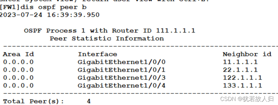
-
配置Trust到DMZ的安全策略
西安校区办公区域需要访问服务器,故需配置trust区域到dmz区域的安全策略:
FW1上:
| [FW1]security-policy [FW1-policy-security]rule name t-to-dmz [FW1-policy-security-rule-t-to-dmz]source-zone trust [FW1-policy-security-rule-t-to-dmz]destination-zone dmz [FW1-policy-security-rule-t-to-dmz]source-address 10.1.0.0 16 [FW1-policy-security-rule-t-to-dmz]action permit [FW1-policy-security-rule-t-to-dmz] dis th 2023-07-24 08:12:24.140 # rule name t-to-dmz source-zone trust destination-zone dmz source-address 10.1.0.0 mask 255.255.0.0 action permit # return |
查看是否能够访问:
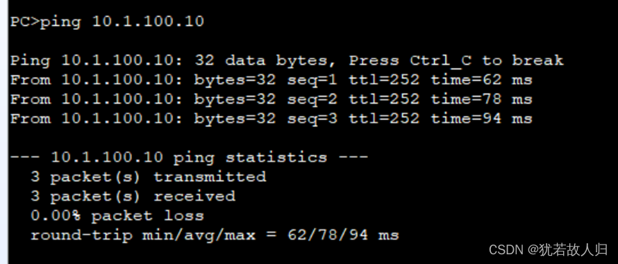
-
配置NAT
要求办公区域能够访问公网,由于没有公网的路由,故在此处配置源NAT转换,使得办公区域的PC能够访问公网。
NAT策略如下:
| //NAT策略: [FW1]nat-policy [FW1-policy-nat]rule name to-isp [FW1-policy-nat-rule-to-isp]source-zone trust [FW1-policy-nat-rule-to-isp]destination-zone untrust [FW1-policy-nat-rule-to-isp]source-address 10.1.0.0 16 [FW1-policy-nat-rule-to-isp]action source-nat easy-ip [FW1-policy-nat-rule-to-isp]dis th 2023-07-24 16:54:17.020 # rule name to-isp source-zone trust destination-zone untrust source-address 10.1.0.0 mask 255.255.0.0 action source-nat easy-ip # return //安全策略: [FW1]security-policy [FW1-policy-security]rule name to-isp [FW1-policy-security-rule-to-isp]source-zone trust [FW1-policy-security-rule-to-isp]destination-zone untrust [FW1-policy-security-rule-to-isp]source-address 10.1.0.0 16 [FW1-policy-security-rule-to-isp]action permit [FW1-policy-security-rule-to-isp]dis th 2023-07-24 08:16:18.960 # rule name to-isp source-zone trust destination-zone untrust source-address 10.1.0.0 mask 255.255.0.0 action permit # Return //配置默认路由并下发 [FW1]ip route-static 0.0.0.0 0 112.1.1.254 [FW1-ospf-1]default-route-advertise |
NAT策略:

安全策略:
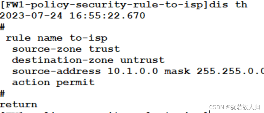
查看办公区域是否能够访问外网:
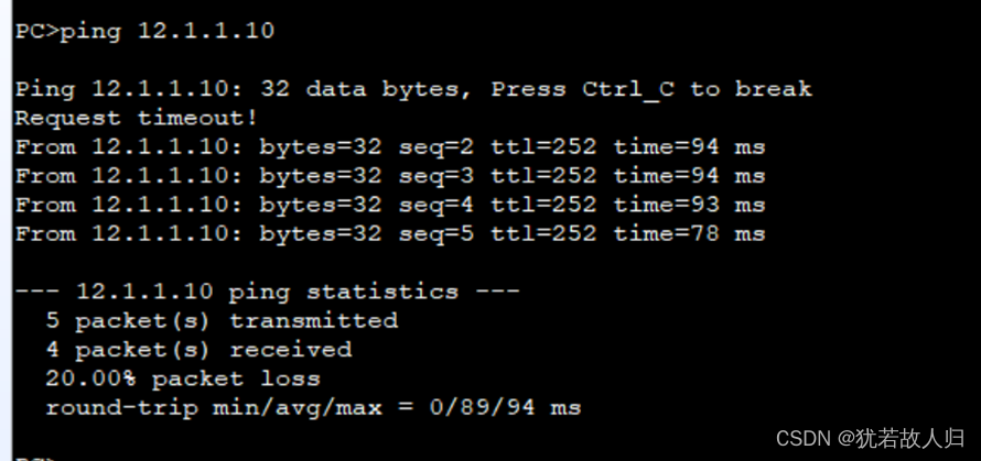
由上可知,办公区域能够正常访问外网。
-
公网访问dmz区域的http服务和STP服务
通过nat-server 进行映射
FW1上:
| [FW1]nat server protocol tcp global 112.1.1.10 80 inside 10.1.100.10 80 [FW1]nat server protocol tcp global 112.1.1.10 21 inside 10.1.101.10 21 [FW1]security-policy [FW1-policy-security]rule name un-to-dmz [FW1-policy-security-rule-un-to-dmz]source-zone untrust [FW1-policy-security-rule-un-to-dmz]destination-zone dmz [FW1-policy-security-rule-un-to-dmz]destination-address 10.1.100.10 32 [FW1-policy-security-rule-un-to-dmz]destination-address 10.1.101.10 32 [FW1-policy-security-rule-un-to-dmz]action permit [FW1-policy-security-rule-un-to-dmz]dis th 2023-07-24 08:25:31.610 # rule name un-to-dmz source-zone untrust destination-zone dmz destination-address 10.1.100.10 mask 255.255.255.255 destination-address 10.1.101.10 mask 255.255.255.255 action permit # return [FW1-policy-security-rule-un-to-dmz]q [FW1-policy-security]q [FW1]dis cu [FW1]dis current-configuration | in nat 2023-07-24 08:28:17.180 nat server 0 protocol tcp global 112.1.1.10 www inside 10.1.100.10 www nat server 1 protocol tcp global 112.1.1.10 ftp inside 10.1.101.10 ftp destination-zone dmz destination-zone untrust destination-zone dmz destination-address 10.1.100.10 mask 255.255.255.255 destination-address 10.1.101.10 mask 255.255.255.255 nat-policy destination-zone untrust action source-nat easy-ip |
公网访问dmz区域的http服务和STP服务:


总部网络所有需求到此已经满足,下面将对分校区进行部署。
<二>、临潼分部配置
需求:
VLAN,MSTP,VLAN间路由、VRRP,OSPF路由配置。PC4属于VLAN 10,PC5属于VLAN20。
下面将在交换机上配置vlan并添加接口,交换机与客户端之间为access链路;接入层接入层与核心交换机之间为Trunk链路;核心交换机之间进行eth-trunk链路捆绑,并允许所有的vlan通过;核心交换机上行链路为access,加入到对应的vlan中。其中交换机7、8配置相似,交换9、10配置相似,具体配置如下:
SW7上:
| // 创建vlan加接口 [R7]v b 10 20 47 [R7]int g0/0/5 [R7-GigabitEthernet0/0/5]p l t [R7-GigabitEthernet0/0/5]p t a v a [R7-GigabitEthernet0/0/5]int g0/0/6 [R7-GigabitEthernet0/0/6]p l t [R7-GigabitEthernet0/0/6]p t a v a [R7-GigabitEthernet0/0/6]q //对8、9口进行捆绑,并允许所有vlan通过 [R7]int Eth-Trunk 1 [R7-Eth-Trunk1]trunkport GigabitEthernet 0/0/8 to 0/0/9 [R7-Eth-Trunk1]dis th # interface Eth-Trunk1 # return [R7-Eth-Trunk1]p l t [R7-Eth-Trunk1]p t a v a [R7-Eth-Trunk1]q //上行链路加到vlan 47 中 [R7]int g0/0/1 [R7-GigabitEthernet0/0/1]p l a [R7-GigabitEthernet0/0/1]p d v 47 |
SW8上:
| [R8]v b 10 20 48 [R8]int g0/0/5 [R8-GigabitEthernet0/0/5]p l t [R8-GigabitEthernet0/0/5]p t a v a [R8-GigabitEthernet0/0/5]int g0/0/6 [R8-GigabitEthernet0/0/6]p l t [R8-GigabitEthernet0/0/6]p t a v a [R8-GigabitEthernet0/0/6]int g0/0/2 [R8-GigabitEthernet0/0/2]p l a [R8-GigabitEthernet0/0/2] p d v 48 [R8-GigabitEthernet0/0/2]q [R8]int Eth-Trunk 1 [R8-Eth-Trunk1]trunkport GigabitEthernet 0/0/8 to 0/0/9 [R8-Eth-Trunk1]p l t [R8-Eth-Trunk1]p t a v a |
SW9上:
| [R9]v b 10 20 [R9]int g0/0/1 [R9-GigabitEthernet0/0/1]p l a [R9-GigabitEthernet0/0/1]p d v 10 [R9-GigabitEthernet0/0/1]int g0/0/5 [R9-GigabitEthernet0/0/5]p l t [R9-GigabitEthernet0/0/5]p t a v a [R9-GigabitEthernet0/0/5]int g0/0/6 [R9-GigabitEthernet0/0/6]p l t [R9-GigabitEthernet0/0/6]p t a v a |
SW10上:
| [R10]v b 10 20 [R10]int g0/0/1 [R10-GigabitEthernet0/0/1]p l a [R10-GigabitEthernet0/0/1]p d v 20 [R10-GigabitEthernet0/0/1]int g0/0/5 [R10-GigabitEthernet0/0/5]p l t [R10-GigabitEthernet0/0/5]p t a v a [R10-GigabitEthernet0/0/5]int g0/0/6 [R10-GigabitEthernet0/0/6]p l t [R10-GigabitEthernet0/0/6]p t a v a |
下面对MSTP进行配置,使得SW7为VLAN10的根桥,VLAN 20的次根。SW8为VLAN20的根桥,VLAN10的次根。
SW7上:
| R7]stp region-configuration [R7-mst-region]region-name SLG-group13 [R7-mst-region]revision-level 1 [R7-mst-region]instance 1 vlan 10 [R7-mst-region]instance 2 vlan 20 [R7-mst-region]active region-configuration [R7-mst-region]dis th # stp region-configuration region-name SLG-group13 revision-level 1 instance 1 vlan 10 instance 2 vlan 20 active region-configuration # return |
此处配置,SW7、SW8、SW9、SW10上均一致:
SW8:
| [R8]stp region-configuration [R8-mst-region] region-name SLG-group13 [R8-mst-region] revision-level 1 [R8-mst-region] instance 1 vlan 10 [R8-mst-region] instance 2 vlan 20 [R8-mst-region] active region-configuration [R8-mst-region]dis th # stp region-configuration region-name SLG-group13 revision-level 1 instance 1 vlan 10 instance 2 vlan 20 active region-configuration # return |
SW9:
| [R9]stp region-configuration [R9-mst-region] region-name SLG-group13 [R9-mst-region] revision-level 1 [R9-mst-region] instance 1 vlan 10 [R9-mst-region] instance 2 vlan 20 [R9-mst-region] active region-configuration |
SW10 :
| [R10-mst-region] region-name SLG-group13 [R10-mst-region] revision-level 1 [R10-mst-region] instance 1 vlan 10 [R10-mst-region] instance 2 vlan 20 [R10-mst-region] active region-configuration [R10-mst-region] [R10-mst-region]dis th # stp region-configuration region-name SLG-group13 revision-level 1 instance 1 vlan 10 instance 2 vlan 20 active region-configuration # return |
下面修改相关instance的优先级使得SW7成为vlan 10 的根,SW8成为vlan 20 的根:
SW7上 :
| [R7]stp instance 1 priority 0 [R7]stp instance 2 priority 4096 |
SW8上:
| [R8]stp instance 1 priority 4096 [R8]stp instance 2 priority 0 |
查看配置是否达到需求:
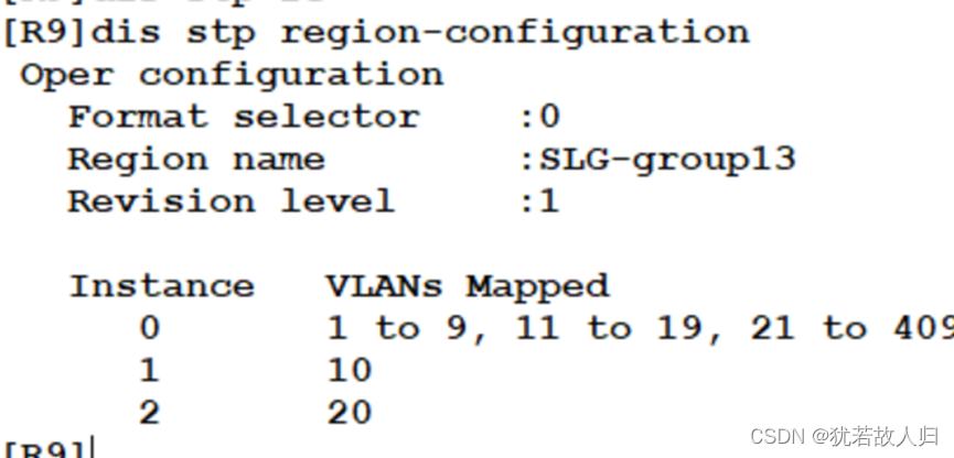

将连接终端的接口配置为边缘端口。
SW9:
| [R9-GigabitEthernet0/0/1]stp edged-port enable |
SW10上:
| [R10-GigabitEthernet0/0/1]stp edged-port enable |
下面将对vlan间路由进行配置,使得SW7在VRRP中为VLAN10的Master,VLAN20的Backup。
SW8在VRRP中为VLAN20的Master,VLAN10的Backup。
SW7上:
| [R7-Vlanif10]ip add 10.2.1.1 24 [R7-Vlanif10]vlan 20 [R7-Vlanif20]ip add 10.2.2.1 24 [R7-Vlanif10]vrrp vrid 1 virtual-ip 10.2.1.113 [R7-Vlanif10]vrrp vrid 1 priority 200 [R7-Vlanif10]vrrp vrid 1 preempt-mode timer delay 60 [R7-Vlanif10]vrrp vrid 1 track interface GigabitEthernet 0/0/1 reduced 120 [R7-Vlanif10]dis th # interface Vlanif10 ip address 10.2.1.1 255.255.255.0 vrrp vrid 1 virtual-ip 10.2.1.113 vrrp vrid 1 priority 200 vrrp vrid 1 preempt-mode timer delay 60 vrrp vrid 1 track interface GigabitEthernet0/0/1 reduced 120 # return [R7-Vlanif10]int vlan 20 [R7-Vlanif20]vrrp vrid 2 virtual-ip 10.2.2.113 |
SW8上:
| [R8-Vlanif10]ip add 10.2.1.2 24 [R8-Vlanif10]int vlan 20 [R8-Vlanif20]ip add 10.2.2.2 24 [R8-Vlanif20]vrrp vrid 2 virtual-ip 10.2.2.113 [R8-Vlanif20]vrrp vrid 2 priority 200 [R8-Vlanif20]vrrp vrid 2 preempt-mode timer delay 60 [R8-Vlanif20]vrrp vrid 2 track interface GigabitEthernet 0/0/2 reduced 120 [R8-Vlanif20]dis th # interface Vlanif20 ip address 10.2.2.2 255.255.255.0 vrrp vrid 2 virtual-ip 10.2.2.113 vrrp vrid 2 priority 200 vrrp vrid 2 preempt-mode timer delay 60 vrrp vrid 2 track interface GigabitEthernet0/0/2 reduced 120 # return [R8-Vlanif20]int vlan 10 [R8-Vlanif10]vrrp vrid 1 virtual-ip 10.2.1.113 |
查看现象:
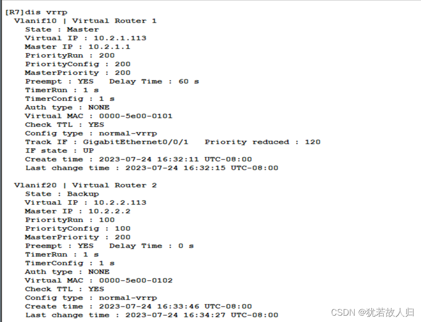

下面对全网路由进行配置:
SW7上:
| [R7]int vlan 47 [R7-Vlanif47]ip add 192.168.47.254 24 [R7-ospf-1]area 2 [R7-ospf-1-area-0.0.0.2]network 192.168.47.0 0.0.0.255 [R7-ospf-1-area-0.0.0.2]network 10.2.1.0 0.0.0.255 [R7-ospf-1-area-0.0.0.2]network 10.2.2.0 0.0.0.255 [R7-ospf-1]silent-interface Vlanif 10 [R7-ospf-1]silent-interface Vlanif 20 |
SW8上;
| [R8]int vlan 48 [R8-Vlanif48]ip add 192.168.48.254 24 [R8-Vlanif48]ospf 1 [R8-ospf-1]area 2 [R8-ospf-1-area-0.0.0.2]network 192.168.48.0 0.0.0.255 [R8-ospf-1-area-0.0.0.2]network 10.2.1.0 0.0.0.255 [R8-ospf-1-area-0.0.0.2]network 10.2.2.0 0.0.0.255 [R8-ospf-1]silent-interface Vlanif 10 [R8-ospf-1]silent-interface Vlanif 20 |
R4上:
| [R4]ospf 1 [R4-ospf-1]area 2 [R4-ospf-1-area-0.0.0.2]network 192.168.47.0 0.0.0.255 [R4-ospf-1-area-0.0.0.2]network 192.168.48.0 0.0.0.255 [R4-ospf-1-area-0.0.0.2]q [R4]ip route-static 0.0.0.0 0 24.1.1.254 [R4-ospf-1]default-route-advertise |
下面做源Nat地址转换,使临潼校区能够访问公网:
R4上:
| [R4]acl 2000 [R4-acl-basic-2000]rule permit source 10.2.0.0 0.0.255.255 [R4-acl-basic-2000]q [R4]int g4/0/0 [R4-GigabitEthernet4/0/0]nat outbound 2000 |
访问公网联通性测试:
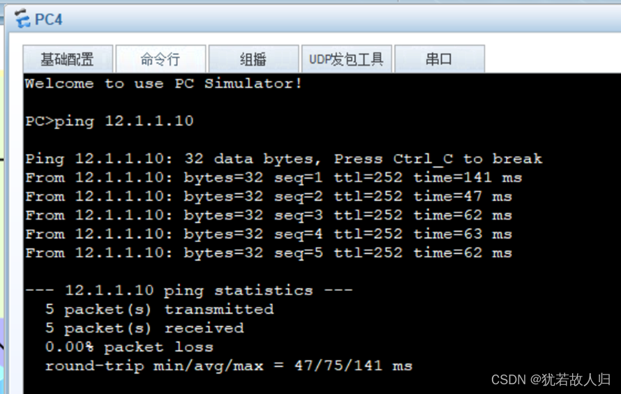
由上,临潼校区的所有需求已经满足,下面将对汉中分校的设备进行配置。
<三>、汉中分部配置(单臂路由,NAT配置)
创建vlan加接口,与客户端相连为access,上行口为Trunk,允许所有vlan通过。
SW11上:
| [SW11]v b 10 20 [SW11]int g0/0/1 [SW11-GigabitEthernet0/0/1]p l a [SW11-GigabitEthernet0/0/1]p d v 10 [SW11-GigabitEthernet0/0/1]int g0/0/2 [SW11-GigabitEthernet0/0/2]p l a [SW11-GigabitEthernet0/0/2]p d v 20 [SW11-GigabitEthernet0/0/2]int g0/0/24 [SW11-GigabitEthernet0/0/24]p l t [SW11-GigabitEthernet0/0/24]p t a v a |
R3上划分子接口:
| [R3]int g0/0/0.10 [R3-GigabitEthernet0/0/0.10]dot1q termination vid 10 [R3-GigabitEthernet0/0/0.10]arp broadcast enable [R3-GigabitEthernet0/0/0.10]dis th [V200R003C00] # interface GigabitEthernet0/0/0.10 dot1q termination vid 10 arp broadcast enable # return [R3-GigabitEthernet0/0/0.10]q [R3]int g0/0/0.20 [R3-GigabitEthernet0/0/0.20]dot1q termination vid 20 [R3-GigabitEthernet0/0/0.20]arp broadcast enable [R3-GigabitEthernet0/0/0.20]ip add 10.3.2.113 24 [R3-GigabitEthernet0/0/0.20]q //公网接口 [R3]int g3/0/0 [R3-GigabitEthernet3/0/0]ip add 23.1.1.3 24 |
访问公网配置:
R3上:
| //配置默认路由 [R3]ip route-static 0.0.0.0 0 23.1.1.254 [R3]acl 2000 [R3-acl-basic-2000]rule permit source 10.3.0.0 0.0.255.255 [R3-acl-basic-2000]int g3/0/0 [R3-GigabitEthernet3/0/0]nat outbound 2000 |
访问公网测试:

<四>、总校分校DSVPN内网互联配置
为实现内网之间的互通,在总校的R1,临潼校区的R4和汉中校区的R3上配置DSVPN,其中R1作为hub端,R3、R4作为spoke端。三个设备的tunnel口设置在192.168.1.0 网段,R1为.1;R4为.2;R3为.3。下面是相关配置命令:
R1上:
| [R1]int Tunnel 0/0/0 [R1-Tunnel0/0/0]tunnel-protocol gre p2mp [R1-Tunnel0/0/0]ip add 192.168.1.1 24 [R1-Tunnel0/0/0]source GigabitEthernet 0/0/2 [R1-Tunnel0/0/0]nhrp entry multicast d [R1-Tunnel0/0/0]dis th [V200R003C00] # interface Tunnel0/0/0 ip address 192.168.1.1 255.255.255.0 tunnel-protocol gre p2mp source GigabitEthernet0/0/2 nhrp entry multicast dynamic # Return //调整优先级至最大,使其成为DR [R1-Tunnel0/0/0]ospf dr-priority 255 |
R3上:
| [R3]int Tunnel 0/0/0 [R3-Tunnel0/0/0]tunnel-protocol gre p2mp [R3-Tunnel0/0/0]ip add 192.168.1.3 24 [R3-Tunnel0/0/0]source GigabitEthernet 3/0/0 [R3-Tunnel0/0/0]nhrp entry 192.168.1.1 112.1.1.2 register [R3-Tunnel0/0/0]ospf network-type broadcast [R3-Tunnel0/0/0]ospf dr-priority 0 |
R4上:
| [R4]int Tunnel 0/0/0 [R4-Tunnel0/0/0]tunnel-protocol gre p2mp [R4-Tunnel0/0/0]ip add 192.168.1.2 24 [R4-Tunnel0/0/0]source GigabitEthernet 4/0/0 [R4-Tunnel0/0/0]nhrp entry 192.168.1.1 112.1.1.2 register [R4-Tunnel0/0/0]ospf network-type broadcast [R4-Tunnel0/0/0]ospf dr-priority 0 |
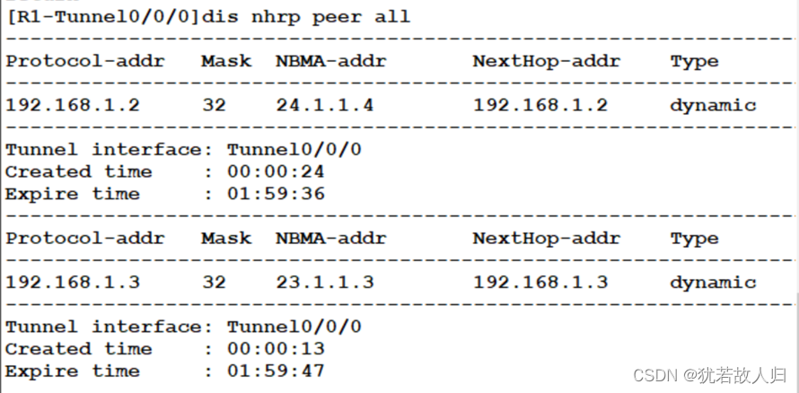
查看nhrp邻居表:
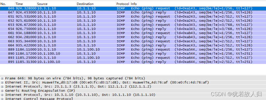
查看注册过程:
下面配置将tunnel 口宣告到area 0区域:
R1上:
| [R1]ospf 1 [R1-ospf-1]area 0 [R1-ospf-1-area-0.0.0.0]network 192.168.1.0 0.0.0.255 |

R3上:
| [R3-ospf-1-area-0.0.0.0]network 192.168.1.0 0.0.0.255 |
R4上:
| [R4-ospf-1-area-0.0.0.0]network 192.168.1.0 0.0.0.255 |
在R1上查看ospf的邻居:

致此,所有业务需求均已满足。
总 结
本项目涉及新建校园的网络搭建,包括西安总校、临潼分校和汉中分校的互联,以及对办公楼宇区域和服务器区域的高可靠性设计,利用双核心实现了稳定性。总体而言,该项目在满足新建校园网络需求的同时,重点关注了网络的高可靠性和安全性。通过冗余链路、协议配置和访问控制等手段,确保了网络的稳定运行和对外访问的安全性。同时,通过DSVPN连接实现校区之间的内网互通,提高了校园网络的整体互联性和通信效率。这样的设计方案为校园网络提供了稳健的基础架构,为未来的拓展和增长提供了良好的支持。
此过程中未包含无线接入部分,拓扑图可查看绑定资源!


