热门标签
热门文章
- 1AI算法工程师 | 02人工智能基础-Python基础(一)开发环境搭建_基于python的人工智能基础开发
- 2Springboot整合Dubbo/ZooKeeper demo_springboot dubbo zk demo
- 3Git怎样用?(下载到本地,和在本地初始化)
- 4C++ 学习(基础语法篇)_c++学习
- 5资深老鸟整理,Java接口自动化测试总结,从0到1自动化..._java自动化
- 6【EasyExcel&Hutool】excel表格的导入和导出,csv文件的导入导出_easyexcel导出excel文件
- 7kali 2023.3新增工具_kali 16进制编辑器
- 8程序员的十年工作创业血泪史,万字长文,仔细读完,受益匪浅_一个java学习站如何盈利
- 9java连接数据库的操作(2):jpa_java 程序 如何使用jpa连接数据库
- 10神经网络训练trick总结
当前位置: article > 正文
【opencv学习】【傅里叶变换】【高通滤波器和低通滤波器】_opencv c++ fft提取高频
作者:羊村懒王 | 2024-02-12 19:11:24
赞
踩
opencv c++ fft提取高频
import cv2
import numpy as np
from matplotlib import pyplot as plt


# 展示图像,封装成函数
def cv_show_image(name, img):
    cv2.imshow(name, img)
    cv2.waitKey(0)  # 等待时间,单位是毫秒,0代表任意键终止
    cv2.destroyAllWindows()

# 高频:图像灰度变化剧烈的部分,一般是边界点
# 低频:图像像素变化变化缓慢的部分

# 高通滤波:只保留高频成分,会使得图像细节增强
# 低通滤波:只保留低频成分,会使得图像变得模糊

# 1. cv2.dft(img, cv2.DFT_COMPLEX_OUTPUT) 进行傅里叶变化
# 参数说明: img表示输入的图片, cv2.DFT_COMPLEX_OUTPUT表示进行傅里叶变化的方法
#
# 2. np.fft.fftshift(img)  将图像中的低频部分移动到图像的中心
# 参数说明:img表示输入的图片
#
# 3. cv2.magnitude(x, y) 将sqrt(x^2 + y^2) 计算矩阵维度的平方根
# 参数说明:需要进行x和y平方的数
#
# 4.np.fft.ifftshift(img) # 进图像的低频和高频部分移动到图像原来的位置
# 参数说明:img表示输入的图片
#
# 5.cv2.idft(img) # 进行傅里叶的逆变化
# 参数说明:img表示经过傅里叶变化后的图片


# =============================================================================
# 图像的DFT
# =============================================================================

img = cv2.imread('images/naruto.jpg', cv2.IMREAD_GRAYSCALE)  # 读取灰度图,DFT是对一个通道计算的
img_float32 = np.float32(img)  # 转成浮点数的,方便DFT计算

# 进行DFT计算
# 但是结果是双通道的,有实部和虚部,无法直接展示,需要转换成图像格式(像素值是0~255)才能展示
dft = cv2.dft(img_float32, flags=cv2.DFT_COMPLEX_OUTPUT)
print(dft.shape)
dft_shift = np.fft.fftshift(dft)  # 将低频的值集中到图像的中间位置,拼接好图像
print(dft_shift.shape)

# 在转成能灰度表示的图像形式,DFT的计算结果是双通道的,是实部和虚部
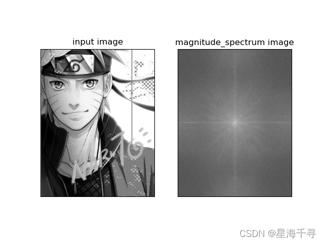
magnitude_spectrum = 20 * np.log(cv2.magnitude(dft_shift[:, :, 0], dft_shift[:, :, 1]))

plt.subplot(1, 2, 1), plt.imshow(img, 'gray')
plt.title('input image'), plt.xticks([]), plt.yticks([])
plt.subplot(1, 2, 2), plt.imshow(magnitude_spectrum, 'gray')
plt.title('magnitude_spectrum image'), plt.xticks([]), plt.yticks([])
plt.show()


# =============================================================================
# 低通滤波器,高通滤波器
# =============================================================================
img = cv2.imread('images/naruto.jpg', cv2.IMREAD_GRAYSCALE)  # 读取灰度图,DFT是对一个通道计算的
img_float32 = np.float32(img)  # 转成浮点数的,方便DFT计算

# 进行DFT计算
# 但是结果是双通道的,有实部和虚部,无法直接展示,需要转换成图像格式(像素值是0~255)才能展示
dft = cv2.dft(img_float32, flags=cv2.DFT_COMPLEX_OUTPUT)
print(dft.shape)
dft_shift = np.fft.fftshift(dft)  # 将低频的值集中到图像的中间位置,拼接好图像
print(dft_shift.shape)

# ============================

# 计算图像的row和col size,以及中心点的位置
rows, cols = img.shape
center_x, center_y = int(rows / 2), int(cols / 2)
mask_len = 50

# 低通滤波器:将高频部分全部过滤,就是远离中心的频率全部掩盖
# 先做个掩码mask,中心部分通过
mask_low = np.zeros((rows, cols, 2), np.uint8)
mask_low[center_x - mask_len: center_x + mask_len, center_y - mask_len: center_y + mask_len] = 1

# 低通滤波器:将低频部分全部过滤,就是中心附近的频率全部掩盖
# 先做个掩码mask,中心部分抑制
mask_high = np.ones((rows, cols, 2), np.uint8)
mask_high[center_x - mask_len: center_x + mask_len, center_y - mask_len: center_y + mask_len] = 0

# IDFT 运用低通滤波器
fshift_low = dft_shift * mask_low  # 进行掩码运算后,得到了过滤后的低通分量
f_ishift_low = np.fft.ifftshift(fshift_low)  # 逆转换,进图像的低频和高频部分移动到图像原来的位置
idft_img_low = cv2.idft(f_ishift_low)  # 逆 DFT
idft_img_low = cv2.magnitude(idft_img_low[:, :, 0], idft_img_low[:, :, 1])  # 求加和平方根

# IDFT 运用高通滤波器
fshift_high = dft_shift * mask_high  # 进行掩码运算后,得到了过滤后的高通分量
f_ishift_high = np.fft.ifftshift(fshift_high)  # 逆转换,进图像的低频和高频部分移动到图像原来的位置
idft_img_high = cv2.idft(f_ishift_high)  # 逆 DFT
idft_img_high = cv2.magnitude(idft_img_high[:, :, 0], idft_img_high[:, :, 1])  # 求加和平方根

plt.subplot(131), plt.imshow(img, cmap='gray'), plt.title('src img')
plt.xticks([]), plt.yticks([])  # 隐藏坐标轴
plt.subplot(132)
plt.imshow(idft_img_low, cmap='gray'), plt.title('low pass img')
plt.xticks([]), plt.yticks([])  # 隐藏坐标轴
plt.subplot(133)
plt.imshow(idft_img_high, cmap='gray'), plt.title('high pass img')
plt.xticks([]), plt.yticks([])  # 隐藏坐标轴
plt.show()
- 1
- 2
- 3
- 4
- 5
- 6
- 7
- 8
- 9
- 10
- 11
- 12
- 13
- 14
- 15
- 16
- 17
- 18
- 19
- 20
- 21
- 22
- 23
- 24
- 25
- 26
- 27
- 28
- 29
- 30
- 31
- 32
- 33
- 34
- 35
- 36
- 37
- 38
- 39
- 40
- 41
- 42
- 43
- 44
- 45
- 46
- 47
- 48
- 49
- 50
- 51
- 52
- 53
- 54
- 55
- 56
- 57
- 58
- 59
- 60
- 61
- 62
- 63
- 64
- 65
- 66
- 67
- 68
- 69
- 70
- 71
- 72
- 73
- 74
- 75
- 76
- 77
- 78
- 79
- 80
- 81
- 82
- 83
- 84
- 85
- 86
- 87
- 88
- 89
- 90
- 91
- 92
- 93
- 94
- 95
- 96
- 97
- 98
- 99
- 100
- 101
- 102
- 103
- 104
- 105
- 106
- 107
- 108
- 109
图像和DFT后的结果

低通和高通的结果

声明:本文内容由网友自发贡献,不代表【wpsshop博客】立场,版权归原作者所有,本站不承担相应法律责任。如您发现有侵权的内容,请联系我们。转载请注明出处:https://www.wpsshop.cn/w/羊村懒王/article/detail/78459
推荐阅读
相关标签


