- 1同样的APP为何在Android 8以后网络感觉变卡?
- 2史上最全!用Pandas读取CSV,看这篇就够了
- 3基础编码管理组件 Example 程序
- 4【实用党】推荐几款实用的AI工具_手绘生成图片
- 5【C语言篇】链表的基本操作-创建链表、插入节点、删除节点、打印链表_链表结构体打印链表程序
- 6【行为识别现状调研1】_多尺度时空特征和运动特征的异常行为识别
- 7QUIC:基于UDP的多路复用安全传输(部分翻译)_quic的多路复用
- 8mysql查询和修改的底层原理_数据库修改的实质是什么
- 9技术的正宗与野路子 c#, AOP动态代理实现动态权限控制(一) 探索基于.NET下实现一句话木马之asmx篇 asp.net core 系列 9 环境(Development、Staging ...
- 10中兴新支点桌面操作系统——一些小而美的功能
S1-FPGA硬件板级原理图实战导学_fpga开发板原理图详解
赞
踩
视频链接
FPGA硬件板级原理图实战导学
【硬件电路设计的方法和技巧-哔哩哔哩】硬件电路设计的方法和技巧01_哔哩哔哩_bilibili(40min)
【高速板级硬件电路设计-哔哩哔哩】 高速板级硬件电路设计1_哔哩哔哩_bilibili (80min)
【硬件板级调试浅谈-哔哩哔哩】 硬件板级调试浅谈01_哔哩哔哩_bilibili (60min)
重点:
1、看手册!& 参考设计!& 芯片FAE!(不同的芯片定义,用法可能存在差异)
2、设计的总体思路:小至大,粗至细
1、硬件板级系统的构成
1.1、最小系统设计
1.1.1、主芯片
1.1.2、时钟 (参考19课)
1.1.3、复位 (参考20课)
1.1.4、存储 (参考21-30课)
1.1.5、系统启动引导顺序-BOOT
1.1.6、烧录程序 & 功能调试
1.2、电源 (实战Power 1~7)
1.2.1、芯片电源需求
1.2.2、芯片上电和下电时序 (4.8节)
【浅谈板级电源设计的三种方法-哔哩哔哩】 浅谈板级电源设计的三种方法_哔哩哔哩_bilibili
1.2.3、功耗评估表格
《7_Series_XPE_2019_1_2.xlsm》
《7-Series-Schematic-Review-Recommendations-xart-040714.xls》
1.3、其他功能模块 (模块化电路设计)
2、7 系列FPGA 简介
Artix 7 FPGA Package Device Pinout Files


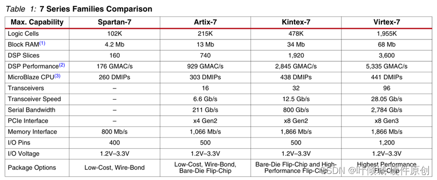
7系列资源表
《数据手册-SMQ7K325TFFG900IP》 P4~9


2.1、A7芯片
《 ug475_7Series_Pkg_Pinout 》

2.2、K7 feature summary
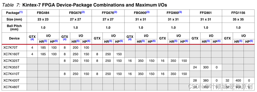
2.2.1、XC7K325TFFG900PKG


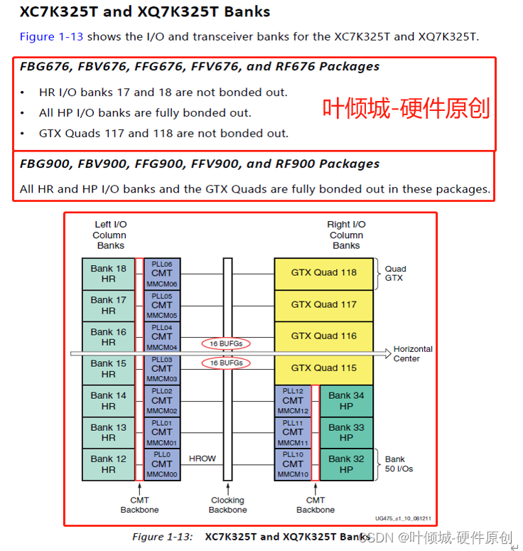
2.2.2、XC7K325TFFG676PKG
注意:一定要根据手册来评估是HR bank还是HP bank,有些芯片bank是三十几,但其是HR bank!
3、xilinx引脚功能介绍(K7为例) ★
3.1、Configuration Pins In Bank 0
《ug470_7Series_Config》 P24-32
《ug480_7Series_XADC》 P16-17
《国微K7系列应用指南_V1.5》
| Pin Name | Description |
| CFGBVS_0 (Input) Dedicated | Configuration Banks Voltage Select 配置组电压选择 // 配置Banks电压选择: VCCO_0电压为3.3V/2.5V时,CFGBVS为高电平,即接到VCCO_0; VCCO_0电压为1.8V/1.5V时,CFGBVS为低电平,即接到GND。 在配置过程中,Bank14和Bank15需要和Bank0电平匹配。 注意:为了避免损害器件,该管脚必须连接到VCCO_0或者GND。// CFGBVS determines the I/O voltage operating range and voltage tolerance for the dedicated configuration bank 0 and for the multi-function configuration pins in banks 14 and 15 in the Spartan-7, Artix-7 and Kintex-7 families. CFGBVS selects the operating voltage for the dedicated bank 0 at all times in all 7 series devices. CFGBVS selects the operating voltage for the multi-function configuration banks 14 and 15 only during configuration. CFGBVS确定了Spartan-7、artix -7和Kintex-7系列中专用配置组0和组14和组15中的多功能配置引脚的I/O电压工作范围和电压公差。CFGBVS在所有7系列设备中始终为专用组0选择工作电压。CFGBVS只在配置时选择多功能组14和15的工作电压。 Connect CFGBVS High or Low per the bank voltage requirements. If the VCCO_0 supply for bank 0 is supplied with 2.5V or 3.3V, then the CFGBVS pin must be tied High (i.e. connected to VCCO_0). Tie CFGBVS to Low (i.e. connected to GND), only if the VCCO_0 for bank 0 is less than or equal to 1.8V. If used during configuration, banks 14 and 15 should match the VCCO level applied to bank 0. 根据组电压要求连接CFGBVS高电平或低电平。如果组0的Vcco_o提供2.5V或3.3V,则CFGBVS引脚必须连接到高(即连接到Vcco)。只有当0组的VCCO_0小于或等于1.8V时,CFGBVS引脚才必须连接到低(即连接到GND)。如果在配置期间使用,组14和15应该匹配应用于组0的VCCO级别。 Caution! To avoid device damage, CFGBVS must be connected correctly to either VCCO_0 or GND. 谨慎!为避免损坏设备,CFGBVS必须正确连接Vcco或GND。 Note: The CFGBVS pin is not available on Virtex-7 HT devices. Virtex-7 HT devices support only 1.8V/1.5V operation for bank 0. 注意:CFGBVS引脚在Virtex-7 HT设备上不可用。Virtex-7 HT设备仅支持1.8V/1.5V的工作bank 0。 |
| M[2:0] (Input) Dedicated 详细讲解见4.4节 | Configuration Mode 配置Mode //配置模式选择位// M[2:0] determine the configuration mode. Connect each mode pin either directly, or via a ≤ 1 kΩ resistor, to VCCO_0 or GND. M[2:0]确定配置模式。 将每个模式引脚直接连接,或通过一个小于或者等于1 kΩ电阻连接到VCCO_0或GND。 |
| PROGRAM_B_0 (Input)Dedicated | Program (bar) 异步复位到配置逻辑(低电平有效)。 //低电平有效复位配置逻辑。 当PROGRAM_B脉冲为低电平时,FPGA配置被清零并启动新的配置序列。 在下降沿启动配置复位,并且配置(即编程)序列在随后的上升沿开始。 为了确保输入稳定的高电平,需要外部连接一个≤4.7kΩ的电阻到VCCO_0。 注意:上电时保持PROGRAM_B为低电平不会使FPGA配置保持复位状态。 而是使用INIT_B来延迟上电配置序列。// Active-Low reset to configuration logic. When PROGRAM_B is pulsed Low, the FPGA configuration is cleared and a new configuration sequence is initiated.Configuration reset initiated upon falling edge, and configuration (i.e. programming) sequence begins upon the following rising edge. 低电平有效复位到配置逻辑。当PROGRAM_B为Low脉冲时,FPGA配置将被清除,并启动新的配置序列。下沿开始配置重置,下沿上升开始配置(即编程)。 Connect PROGRAM_B to an external ≤ 4.7 kΩ pull-up resistor to VCCO_0 to ensure a stable High input, and recommend push-button to GND to enable manual configuration reset. 将PROGRAM_B连接到外部≤4.7 kΩ上拉电阻到Vcco_o,确保稳定的高输入,并建议按下按钮到GND,以实现手动配置复位。 Note: Holding PROGRAM_B Low from power-on does not keep the FPGA configuration in reset. Instead, use INIT_B to delay the power-on configuration sequence. 注意:在上电时保持PROGRAM_B为Low并不会使FPGA配置处于复位状态。请使用INIT_B延迟上电配置顺序。 |
| INIT_B_0 (Bidirectional) (open-drain) Dedicated | Initialization (bar) 初始化 //表示配置存储器的初始化(低电平有效); 当FPGA处于配置复位状态,FPGA正在初始化(清除)其配置存储器时,或者当FPGA检测到配置错误时,FPGA将此引脚驱动为低电平。 完成FPGA初始化过程后,INIT_B释放到高阻态,此时外部电阻预计将INIT_B拉高。 在上电期间,INIT_B可以在外部保持低电平,以在初始化过程结束时停止上电配置序列。 当初始化过程后在INIT_B输入检测到高电平时,FPGA继续执行M [2:0]引脚设置所指示的配置序列的其余部分。 将INIT_B连接至一个≤4.7kΩ的上拉电阻至VCCO_0,以确保从低到高的转换。// Active-Low FPGA initialization pin or configuration error signal. The FPGA drives this pin Low when the FPGA is in a configuration reset state, when the FPGA is initializing (clearing) its configuration memory, or when the FPGA has detected a configuration error. Upon completing the FPGA initialization process, INIT_B is released to high-Z at which time an external resistor is expected to pull INIT_B High. INIT_B can externally be held Low during power-up to stall the power-on configuration sequence at the end of the initialization process. When a High is detected at the INIT_B input after the initialization process, the FPGA proceeds with the remainder of the configuration sequence dictated by the M[2:0] pin settings. 低电平有效 FPGA初始化引脚或配置错误信号。当FPGA处于配置重置状态时,当FPGA初始化(清除)其配置内存时,或者当FPGA检测到配置错误时,FPGA将该引脚驱动为Low。在完成FPGA初始化过程后,INIT_B被释放到High - z,此时一个外部电阻预计将INIT_B拉到高。在上电过程中,INIT_B可以从外部保持为Low,以暂停初始化过程结束时的上电配置顺序。当初始化过程后在INIT_B输入端检测到High时,FPGA继续执行由M[2:0]引脚设置指定的其余配置顺序。 Connect INIT_B to a ≤ 4.7 kΩ pull-up resistor to VCCO_0 to ensure clean Low-to-High transitions. 将INIT_B连接到≤4.7 kΩ上拉电阻到Vcco_0,以确保干净利落的由低到高转换。 |
| DONE_0 (Bidirectional) Dedicated | Done 配置完成 //DONE表示配置成功完成(高电平有效)作为输出,这个引脚说明配置过程已经完成;作为输入,配置为低电平可以延迟启动。// A High signal on the DONE pin indicates completion of the configuration sequence. The DONE output is an open-drain output by default. DONE引脚上的高信号表示配置序列的完成。在默认情况下DONE输出是开漏输出。 Note: DONE has an internal pull-up resistor of approximately 10 kΩ. There is no setup/hold requirement for the DONE register. 注意:DONE有一个内部上拉电阻大约10 kΩ。DONE寄存器没有设置/保持要求。 |
| TCK_0 (Input) Dedicated | IEEE Std 1149.1 (JTAG) Test Clock Jtag测试时钟 //JTAG时钟// Clock for all devices on a JTAG chain. Connect to Xilinx cable header's TCK pin. Treat as a critical clock signal and buffer the cable header TCK signal as necessary for multiple device JTAG chains. If the TCK signal is buffered, connect the buffer input to an external weak(e.g. 10 kΩ) pull-up resistor to maintain a valid High when no cable is connected. JTAG链上所有设备的时钟。连接到Xilinx下载器的TCK引脚。对待关键时钟信号和缓冲器,下载器的TCK信号JTAG链需要做为复合器件。如果TCK信号是缓冲的,将缓冲输入连接到一个外部弱信号(例如10 kΩ)上拉电阻,在没有下载器连接时保持有效的高。 |
| TDI_0 (Input) Dedicated | JTAG Test Data Input Jtag数据输入 //JTAG数据输入// JTAG chain serialized data input. For an isolated device or for the first device in a JTAG chain, connect to Xilinx cable header's TDI pin. Otherwise, when the FPGA is not the first device in a JTAG chain, connect to the TDO pin of the upstream JTAG device in the JTAG scan chain. JTAG链序列化数据输入。对于隔离设备或JTAG链中的第一个设备,连接到Xilinx电缆头的TDI引脚。否则,当FPGA不是JTAG扫描链中的第一个设备时,请连接到JTAG扫描链中上游JTAG设备的TDO引脚。 |
| TDO_0 (Output)Dedicated | JTAG Test Data Output Jtag数据输出 //JTAG数据输出// JTAG chain serialized data output. For an isolated device or for the last device in a JTAG chain, connect to Xilinx cable header's TDO pin. Otherwise, when the FPGA is not the last device in a JTAG chain, connect to the TDI pin of the downstream JTAG device in the JTAG scan chain. JTAG链序列化数据输出。对于隔离设备或JTAG链中的最后一个设备,连接到Xilinx下载器的TDO引脚。否则,当FPGA不是JTAG扫描链中的最后一个设备时,请连接到JTAG扫描链中下游JTAG设备的TDI引脚。 |
| TMS_0 (Input)Dedicated | JTAG Test Mode Select Jtag模式选择 //JTAG模式选择// Mode select for all devices on a JTAG chain. Connect to Xilinx cable header's TMS pin. Buffer the cable header TMS signal as necessary for multiple device JTAG chains. If the TMS signal is buffered, connect the buffer input to an external weak (e.g. 10 kΩ) pull-up resistor to maintain a valid High when no cable is connected. 为JTAG链上的所有设备选择模式。连接到Xilinx下载器的TMS引脚。对待关键时钟信号和缓冲器,下载器的TMS信号JTAG链需要做为复合器件。如果TMS信号被缓冲,将缓冲输入连接到外部弱(例如10 kΩ)上拉电阻,以在没有下载器连接时保持有效的高。 |
3.2、Configuration Pins In Bank 14 & 15
《ug470_7Series_Config》 P24-32
3.3、Other Pins
3.4、Xilinx FPGA的高速GTx 接口 (★)
Xilinx的针对Gigabit应用的FPGA基本都会集成一些高速串行接口,统称为Gigabit Transceiver(GTx),xilinx的7系列FPGA根据不同的器件类型,集成了GTP、GTX、GTH以及GTZ四种串行高速收发器。
《ug475_7Series_Pkg_Pinout》 P31
7系列FPGA集成的GTx及性能
| 类型 | 最高性能Gbps | 收发器 最大数量 | 峰值带宽Gbps | |
| Artix-7 | GTP | 6.6 | 16 | 211Gb/s |
| Kintex-7 | GTX | 12.5 | 32 | 800Gb/s |
| Zynq-7000 | GTX | 12.5 | 16 | 400Gb/s |
| Virtex-7 | GTX/GTH/GTZ | 12.5/13.1/28.05 | 56/96/16 | 2,784Gb/s |
3.5、Xilinx FPGA中电源管脚 (详解4.7节)
《 ds182_Kintex_7_Data_Sheet 》 P1-
对于kintex7系列,通常咱们使用需要使用以下电源轨:
| Name | Description |
| VCCINT FPGA内部核心电压 | 其不损坏FPGA器件的范围为-0.5V~1.1V。 对于-3、-2、-2LE(1.0V)、-1、-1M和-1LM的kintex7系列,正常工作电压为0.97V~1.03V,推荐工作电压为1.00V。 对于-2LE(0.9V)的kintex7系列,正常工作电压为0.87V~0.93V,推荐工作电压为0.90V。 对于-2LI(0.95V)的kintex7系列,正常工作电压为0.93V~0.97V,推荐工作电压为0.95V。 |
| VCCAUX 辅助供电电压 | 其不损坏FPGA器件的范围为-0.5V~2.0V。正常工作电压为1.71V~1.89V。推荐工作电压为1.80V。 |
| VCCBRAM 内部Block RAM的供电电压 | 其不损坏FPGA器件的范围为-0.5V~1.1V。 对于-3、-2、-2LE(1.0V)、-1、-1M和-1LM的kintex7系列,正常工作电压为0.97V~1.03V,推荐工作电压为1.00V。 对于 -2LE(0.9V)的kintex7系列,正常工作电压为0.87V~0.93V,推荐工作电压为0.90V。 对于 -2LI(0.95V)的kintex7系列,正常工作电压为0.93V~0.97V,推荐工作电压为0.95V。 |
| VCCO | 1、对于HR BANK的接口电压来说,需要与外部器件的信号电平保持一致,其不损坏FPGA器件的范围为-0.5V~3.6V。正常工作电压为1.14V~3.465V。推荐工作电压与外部信号电平一致即可。 |
| 2、对于HP BANK的接口电压来说,需要与外部器件的信号电平保持一致,其不损坏FPGA器件的范围为-0.5V~2.0V。正常工作电压为1.14V~1.89V。推荐工作电压与外部信号电平一致即可。 | |
| VCCAUX_IO IO辅助电压 | 其不损坏FPGA器件的范围为-0.5V~2.06V。正常工作电压为1.14V~1.89V/2.06V。推荐工作电压为1.8V。 |
| VCCADC XADC的 供电电压 | 其不损坏FPGA器件的范围为-0.5V~2.0V。正常工作电压为1.71V~1.89V。推荐工作电压为1.80V。 |
| MGTAVCC GTX收发器 核心电压 | 其不损坏FPGA器件的范围为-0.5V~1.1V。对于QPLL≤10.3125GHz的应用,正常工作电压为0.97V~1.08V,推荐工作电压为1.00V。对于对于QPLL>10.3125GHz的应用,正常工作电压为1.02V~1.08V,推荐工作电压为1.05V。 |
| MGTAVTT GTX收发器 终端匹配电压 | 其不损坏FPGA器件的范围为-0.5V~1.32V。正常工作电压为1.17V~1.23V。推荐工作电压为1.20V。 |
| MGTVCCAUX GTX收发器 辅助电压 | 其不损坏FPGA器件的范围为-0.5V~1.935V。正常工作电压为1.75V~1.85V。推荐工作电压为1.80V。 |
| MGTAVTTRCAL GTX收发器 校正电压 | 其不损坏FPGA器件的范围为-0.5V~1.32V。正常工作电压为1.17V~1.23V。推荐工作电压为1.20V。 |
4、xilinx K7 设计注意事项(K7为例) ★
4.1、Xilinx FPGA中HR、HD、HP bank
4.2、DCI技术概述
4.3、FPGA配置的流程
4.3.1、FPGA配置流程图
4.3.2、JTAG烧写SPI/BPI Flash
4.3.3、BPI和SPI的区别
4.3.4、select MAP与BPI配置模式的比较
4.4、Xilinx FPGA模式配置
4.4.1、主模式 (主串、主SPI、主BPI、主selectMAP)
4.4.2、从模式 (从串、从selectMAP)
4.4.3、JTAG模式 (单JTAG调试模式 & 多设备配置模式)
4.5、Xilinx 7 系列的时钟资源
4.6、XADC模块
4.7、Xilinx FPGA 的高速MGTx电路设计注意点
4.8、电源时序 & 电容取值 (★)


