
- 1数学建模【对粒子群算法中惯性权重和学习因子的改进】_粒子群算法惯性因子
- 2若以框架学习(3),echarts结合后端数据展示,暂时完结。_ruoyi echarts
- 3ue4 umg帧动画_ue umg播放flipbook
- 4Flink - Table API UDF --- 用户自定义函数_flink numeric
- 5gitee与github双向自动同步的方法_gitee同步github
- 6揭示C++设计模式中的实现结构及应用——结构型设计模式_c++ 结构设计模式
- 7TF-IDF关键词提取算法_tfidf提取关键词_实训2 使用tf-idf算法提取关键词 实现基于tf-idf算法的新闻文本关键词提取,利用tf
- 8模型导入问题解析【unity3d教程】
- 9Yakit基本使用
- 10又一个对标Sora的AI视频工具,Dream Machine,开始免费试用
ARM64 SMP多核启动详解2(psci)_cpu psci
赞
踩
1. 支持psci情况
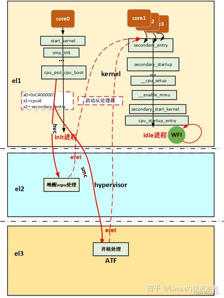
上面说了pin-table的多核启动方式,看似很繁琐,实际上并不复杂,无外乎主处理器唤醒从处理器到指定地址上去执行指令,说他简单是相对于功能来说的,因为他只是实现了从处理器的启动,仅此而已,所以,现在社区几乎很少使用spin-table这种方式,取而代之的是psci,他不仅可以启动从处理器,还可以关闭,挂起等其他核操作,现在基本上arm64平台上使用多核启动方式都是psci。下面我们来揭开他神秘的面纱,其实理解了spin-table的启动方式,psci并不难(说白了也是需要主处理器给从处理器一个启动地址,然后从处理器从这个地址执行指令,实际上比这要复杂的多)。
首先,我们先来看下设备树cpu节点对psci的支持:
arch/arm64/boot/dts/xxx.dtsi:
  cpu0: cpu@0 {
                 device_type = "cpu";
                 compatible = "arm,armv8";
                 reg = <0x0>;
                 enable-method = "psci";
       };

  psci {
                compatible = "arm,psci";
                method = "smc";
                cpu_suspend = <0xC4000001>;
                cpu_off = <0x84000002>;
                cpu_on = <0xC4000003>;
        };
- 1
- 2
- 3
- 4
- 5
- 6
- 7
- 8
- 9
- 10
- 11
- 12
- 13
- 14
- 15
psci节点的详细说明可以参考内核文档:Documentation/devicetree/bindings/arm/psci.txt
可以看到现在enable-method 属性已经是psci,说明使用的多核启动方式是psci, 下面还有psci节点,用于psci驱动使用,method用于说明调用psci功能使用什么指令,可选有两个smc和hvc。其实smc, hvc和svc都是从低运行级别向高运行级别请求服务的指令,我们最常用的就是svc指令了,这是实现系统调用的指令。高级别的运行级别会根据传递过来的参数来决定提供什么样的服务。smc是用于陷入el3(安全), hvc用于陷入el2(虚拟化, 虚拟化场景中一般通过hvc指令陷入el2来请求唤醒vcpu), svc用于陷入el1(系统)。
注:本文只讲解smc陷入el3启动多核的情况。
下面开始分析源代码:
我们都知道armv8将异常等级分为el0 - el3,其中,el3为安全监控器,为了实现对它的支持,arm公司设计了一种firmware叫做ATF(ARM Trusted firmware),下面是atf源码readme.rst文件的一段介绍:
Trusted Firmware-A (TF-A) provides a reference implementation of
secure world software forArmv7-A and Armv8-A, including a
Secure Monitorexecuting at Exception Level 3 (EL3). It
implements various Arm interface standards, such as:
- The
Power State Coordination Interface (PSCI)_- Trusted Board Boot Requirements (TBBR, Arm DEN0006C-1)
SMC Calling Convention_System Control and Management Interface (SCMI)_Software Delegated Exception Interface (SDEI)_
ATF代码运行在EL3, 是实现安全相关的软件部分固件,其中会为其他特权级别提供服务,也就是说提供了在EL3中服务的手段,我们本文介绍的PSCI的实现就是在这里面,本文不会过多的讲解
(注:其实本文只会涉及到atf如何响应服务el1的smc发过来的psci的服务请求,仅此而已,有关ATF(Trustzone)请参考其他资料)。
下面从源代码角度分析服务的注册处理流程:
2. 六成
2.1 bl31处理总体流程
atf/bl31/aarch64/bl31_entrypoint.S:    //架构相关

bl31_entrypoint
->el3_entrypoint_common
_exception_vectors=runtime_exceptions   //设置el3的异常向量表
->bl      bl31_early_platform_setup   //跳转到平台早期设置
->bl      bl31_plat_arch_setup    //跳转到平台架构设置
-> bl      bl31_main  //跳转到bl31_main   atf/bl31/aarch64/bl31_main.c:
->NOTICE("BL31: %s\n", version_string);  //打印版本信息
->NOTICE("BL31: %s\n", build_message); //打印编译信息
->bl31_platform_setup   //执行平台设置
-> /* Initialize the runtime services e.g. psci. */  初始化运行时服务 如psci
 INFO("BL31: Initializing runtime services\n") //打印log信息
->runtime_svc_init   //调用各种运行时服务历程
...
- 1
- 2
- 3
- 4
- 5
- 6
- 7
- 8
- 9
- 10
- 11
- 12
- 13
- 14
- 15
2.2 服务注册
下面的宏是用于注册运行时服务的接口,每种服务通过它来注册:
/*
   * Convenience macro to declare a service descriptor   定义运行时服务描述符结构的宏
   */
  #define DECLARE_RT_SVC(_name, _start, _end, _type, _setup, _smch) \
          static const rt_svc_desc_t __svc_desc_ ## _name \
                  __section("rt_svc_descs") __used = { \  //结构放在rt_svc_descs段中
                          .start_oen = _start, \
                          .end_oen = _end, \
                          .call_type = _type, \
                          .name = #_name, \
                          .init = _setup, \
                          .handle = _smch }

链接脚本中:
bl31/bl31.ld.S:
...
.rodata . : {

 __RT_SVC_DESCS_START__ = .; rt_svc_descs段开始
           KEEP(*(rt_svc_descs))  //rt_svc_descs段
  __RT_SVC_DESCS_END__ = .;  rt_svc_descs段结束

}
...

- 1
- 2
- 3
- 4
- 5
- 6
- 7
- 8
- 9
- 10
- 11
- 12
- 13
- 14
- 15
- 16
- 17
- 18
- 19
- 20
- 21
- 22
- 23
- 24
在标准的运行时服务中将服务初始化和处理函数放到rt_svc_descs段中,供调用。
services/std_svc/std_svc_setup.c:

  DECLARE_RT_SVC(
                  std_svc,

                  OEN_STD_START,
                  OEN_STD_END,
                  SMC_TYPE_FAST,
                  std_svc_setup,//初始化
                  std_svc_smc_handler //处理
  );
- 1
- 2
- 3
- 4
- 5
- 6
- 7
- 8
- 9
- 10
- 11
在runtime_svc_init函数中,调用每一个通过DECLARE_RT_SVC注册的服务,其中包括std_svc服务:
 for (index = 0; index < RT_SVC_DECS_NUM; index++) {
                  rt_svc_desc_t *service = &rt_svc_descs[index];
                  ...
                    rc = service->init(); //调用每一个注册的运行时服务的设置函数
                  ...
                  }
- 1
- 2
- 3
- 4
- 5
- 6
2.3 运行时服务初始化处理
std_svc_setup (主要关注设置psci操作集)
std_svc_setup  //services/std_svc/std_svc_setup.c
->psci_setup //lib/psci/pegsci_setup.c
 ->plat_setup_psci_ops   //设置平台的psci操作    调用平台的plat_setup_psci_ops函数去设置psci操作 eg:qemu平台
  ->*psci_ops = &plat_qemu_psci_pm_ops;
   static const plat_psci_ops_t plat_qemu_psci_pm_ops = {
    .cpu_standby = qemu_cpu_standby,
    .pwr_domain_on = qemu_pwr_domain_on,
    .pwr_domain_off = qemu_pwr_domain_off,
    .pwr_domain_suspend = qemu_pwr_domain_suspend,
    .pwr_domain_on_finish = qemu_pwr_domain_on_finish,
    .pwr_domain_suspend_finish = qemu_pwr_domain_suspend_finish,
    .system_off = qemu_system_off,
    .system_reset = qemu_system_reset,
    .validate_power_state = qemu_validate_power_state,
    .validate_ns_entrypoint = qemu_validate_ns_entrypoint
    };
- 1
- 2
- 3
- 4
- 5
- 6
- 7
- 8
- 9
- 10
- 11
- 12
- 13
- 14
- 15
- 16
- 17
可以看到,在遍历每一个注册的运行时服务的时候,会导致std_svc_setup调用,其中会做psci操作集的设置,操作集中我们可以看到对核电源的管理的接口如:核上电,下电,挂起等,我们主要关注上电 .pwr_domain_on = qemu_pwr_domain_on,这个接口当我们主处理器boot从处理器的时候会用到。
2.4 运行时服务触发和处理
smc指令触发进入el3异常向量表:
runtime_exceptions  //el3的异常向量表
->sync_exception_aarch64
->handle_sync_exception
->smc_handler64
->   	  ¦* Populate the parameters for the SMC handler.
          ¦* We already have x0-x4 in place. x5 will point to a cookie (not used
          ¦* now). x6 will point to the context structure (SP_EL3) and x7 will
          ¦* contain flags we need to pass to the handler Hence save x5-x7.
          ¦*
          ¦* Note: x4 only needs to be preserved for AArch32 callers but we do it
          ¦*       for AArch64 callers as well for convenience
          ¦*/
         stp     x4, x5, [sp, #CTX_GPREGS_OFFSET + CTX_GPREG_X4]  //保存x4-x7到栈
         stp     x6, x7, [sp, #CTX_GPREGS_OFFSET + CTX_GPREG_X6]

       /* Save rest of the gpregs and sp_el0*/
         save_x18_to_x29_sp_el0

       mov     x5, xzr  //x5清零
       mov     x6, sp //sp保存在x6

       /* Get the unique owning entity number */ //获得唯一的入口编号
       ubfx    x16, x0, #FUNCID_OEN_SHIFT, #FUNCID_OEN_WIDTH
       ubfx    x15, x0, #FUNCID_TYPE_SHIFT, #FUNCID_TYPE_WIDTH
       orr     x16, x16, x15, lsl #FUNCID_OEN_WIDTH

       adr     x11, (__RT_SVC_DESCS_START__ + RT_SVC_DESC_HANDLE)

       /* Load descriptor index from array of indices */
       adr     x14, rt_svc_descs_indices  //获得服务描述 标识数组
       ldrb    w15, [x14, x16] //根据唯一的入口编号 找到处理函数的 地址
       /*
       ¦* Restore the saved C runtime stack value which will become the new
       ¦* SP_EL0 i.e. EL3 runtime stack. It was saved in the 'cpu_context'
       ¦* structure prior to the last ERET from EL3.
       ¦*/
       ldr     x12, [x6, #CTX_EL3STATE_OFFSET + CTX_RUNTIME_SP]

       /*
       ¦* Any index greater than 127 is invalid. Check bit 7 for
       ¦* a valid index
       ¦*/
       tbnz    w15, 7, smc_unknown

       /* Switch to SP_EL0 */
       msr     spsel, #0

          /*
          ¦* Get the descriptor using the index
          ¦* x11 = (base + off), x15 = index
          ¦*
          ¦* handler = (base + off) + (index << log2(size))
       ¦*/
       lsl     w10, w15, #RT_SVC_SIZE_LOG2
       ldr     x15, [x11, w10, uxtw]

       /*
       ¦* Save the SPSR_EL3, ELR_EL3, & SCR_EL3 in case there is a world
       ¦* switch during SMC handling.
       ¦* TODO: Revisit if all system registers can be saved later.
       ¦*/
  	   mrs     x16, spsr_el3 //spsr_el3保存在x16
       mrs     x17, elr_el3 //elr_el3保存在x17
  	   mrs     x18, scr_el3  //scr_el3保存在x18
       stp     x16, x17, [x6, #CTX_EL3STATE_OFFSET + CTX_SPSR_EL3]  /  x16, x17/保存在栈
       str     x18, [x6, #CTX_EL3STATE_OFFSET + CTX_SCR_EL3] //x18保存到栈

       /* Copy SCR_EL3.NS bit to the flag to indicate caller's security */
       bfi     x7, x18, #0, #1

       mov     sp, x12

       /*
       ¦* Call the Secure Monitor Call handler and then drop directly into
       ¦* el3_exit() which will program any remaining architectural state
       ¦* prior to issuing the ERET to the desired lower EL.
       ¦*/
#if DEBUG
         cbz     x15, rt_svc_fw_critical_error
#endif
         blr     x15  //跳转到处理函数

         b       el3_exit  //从el3退出会eret 回到el1(后面会讲到)
- 1
- 2
- 3
- 4
- 5
- 6
- 7
- 8
- 9
- 10
- 11
- 12
- 13
- 14
- 15
- 16
- 17
- 18
- 19
- 20
- 21
- 22
- 23
- 24
- 25
- 26
- 27
- 28
- 29
- 30
- 31
- 32
- 33
- 34
- 35
- 36
- 37
- 38
- 39
- 40
- 41
- 42
- 43
- 44
- 45
- 46
- 47
- 48
- 49
- 50
- 51
- 52
- 53
- 54
- 55
- 56
- 57
- 58
- 59
- 60
- 61
- 62
- 63
- 64
- 65
- 66
- 67
- 68
- 69
- 70
- 71
- 72
- 73
- 74
- 75
- 76
- 77
- 78
- 79
- 80
- 81
- 82
- 83
上面其实主要的是找到服务例程,然后跳转执行
下面是跳转的处理函数:
std_svc_smc_handler  //services/std_svc/std_svc_setup.c
->ret = psci_smc_handler(smc_fid, x1, x2, x3, x4,
                  ¦   cookie, handle, flags)
                  ...
} else {
/* 64-bit PSCI function */
  switch (smc_fid) {
  case PSCI_CPU_SUSPEND_AARCH64:
  ret = (u_register_t)
  psci_cpu_suspend((unsigned int)x1, x2, x3);
  break;

  case PSCI_CPU_ON_AARCH64:
  ret = (u_register_t)psci_cpu_on(x1, x2, x3);
  break;

...
}
- 1
- 2
- 3
- 4
- 5
- 6
- 7
- 8
- 9
- 10
- 11
- 12
- 13
- 14
- 15
- 16
- 17
- 18
处理函数根据funid来决定服务,可以看到PSCI_CPU_ON_AARCH64为0xc4000003,这正是设备树中填写的cpu_on属性的id,会委托psci_cpu_on来执行核上电任务。
下面分析是重点:!!!
->psci_cpu_on()  //lib/psci/psci_main.c
 ->psci_validate_entry_point()  //验证入口地址有效性并  保存入口点到一个结构ep中
 ->psci_cpu_on_start(target_cpu, &ep)   //ep入口地址
  ->psci_plat_pm_ops->pwr_domain_on(target_cpu)
   ->qemu_pwr_domain_on  //实现核上电(平台实现)
  /* Store the re-entry information for the non-secure world. */
  ->cm_init_context_by_index()  //重点: 会通过cpu的编号找到 cpu上下文(cpu_context_t),存在cpu寄存器的值,异常返回的时候写写到对应的寄存器中,然后eret,旧返回到了el1!!!
   ->cm_setup_context()  //设置cpu上下文
     -> write_ctx_reg(state, CTX_SCR_EL3, scr_el3);  //lib/el3_runtime/aarch64/context_mgmt.c
              write_ctx_reg(state, CTX_ELR_EL3, ep->pc);  //注: 异常返回时执行此地址  于是完成了cpu的启动!!!
              write_ctx_reg(state, CTX_SPSR_EL3, ep->spsr);
- 1
- 2
- 3
- 4
- 5
- 6
- 7
- 8
- 9
- 10
- 11
psci_cpu_on主要完成开核的工作,然后会设置一些异常返回后寄存器的值(eg:从el1 -> el3 -> el1),重点关注 ep->pc写到cpu_context结构的CTX_ELR_EL3偏移处(从处理器启动后会从这个地址取指执行)。
实际上,所有的从处理器启动后都会从bl31_warm_entrypoint开始执行,在plat_setup_psci_ops中会设置(每个平台都有自己的启动地址寄存器,通过写这个寄存器来获得上电后执行的指令地址)。
大致说一下:主处理器通过smc进入el3请求开核服务,atf中会响应这种请求,通过平台的开核操作来启动从处理器并且设置从处理的一些寄存器eg:scr_el3、spsr_el3、elr_el3,然后主处理器,恢复现场,eret再次回到el1,而处理器开核之后会从bl31_warm_entrypoint开始执行,最后通过el3_exit返回到el1的elr_el3设置的地址。
分析到这atf的分析到此为止,atf中主要是响应内核的snc的请求,然后做开核处理,也就是实际的开核动作,但是从处理器最后还是要回到内核中执行,下面分析内核的处理:注意流程如下:
init/main.c
start_kernel
->boot_cpu_init   //引导cpu初始化  设置引导cpu的位掩码 online active present possible都为true
->setup_arch   // arch/arm64/kernel/setup.c
->  if (acpi_disabled)  //不支持acpi
                  psci_dt_init();     //drivers/firmware/psci.c(psci主要文件) psci初始化 解析设备树 寻找psci匹配的节点
          else
                  psci_acpi_init();   //acpi中允许使用psci情况
->rest_init
->kernel_init
->kernel_init_freeable
->smp_prepare_cpus  //准备cpu,对于每个可能的cpu! cpu_ops[cpu]->cpu_prepare(cpu)    2.set_cpu_present(cpu, true) cpu处于present状态
->do_pre_smp_initcalls   //多核启动之前的调用initcall回调
->smp_init  //smp初始化  kernel/smp.c   会启动其他从处理器
- 1
- 2
- 3
- 4
- 5
- 6
- 7
- 8
- 9
- 10
- 11
- 12
- 13
- 14
我们主要关注两个函数:psci_dt_init和smp_init
psci_dt_init是解析设备树,设置操作函数,smp_init用于启动从处理器。
static const struct of_device_id psci_of_match[] __initconst = {
	{ .compatible = "arm,psci",	.data = psci_0_1_init},
	{ .compatible = "arm,psci-0.2",	.data = psci_0_2_init},
	{ .compatible = "arm,psci-1.0",	.data = psci_1_0_init},
	{},
};

int __init psci_dt_init(void)
{
	struct device_node *np;
	const struct of_device_id *matched_np;
	psci_initcall_t init_fn;
	int ret;

	np = of_find_matching_node_and_match(NULL, psci_of_match, &matched_np);

	if (!np || !of_device_is_available(np))
		return -ENODEV;

	init_fn = (psci_initcall_t)matched_np->data;
	ret = init_fn(np);

	of_node_put(np);
	return ret;
}
- 1
- 2
- 3
- 4
- 5
- 6
- 7
- 8
- 9
- 10
- 11
- 12
- 13
- 14
- 15
- 16
- 17
- 18
- 19
- 20
- 21
- 22
- 23
- 24
- 25
以设备树中compatible = "arm,psci"为例
->psci_0_1_init() //设备树中compatible = "arm,psci"为例
   ->get_set_conduit_method() //根据设备树method属性设置 invoke_psci_fn = __invoke_psci_fn_smc;  (method="smc")
       -> invoke_psci_fn = __invoke_psci_fn_smc
   ->   if (!of_property_read_u32(np, "cpu_on", &id)) {
       psci_function_id[PSCI_FN_CPU_ON] = id;
       psci_ops.cpu_on = psci_cpu_on;  //设置psci操作的开核接口
   }
    ->psci_cpu_on()
     ->invoke_psci_fn()
      ->__invoke_psci_fn_smc()
        -> arm_smccc_smc(function_id, arg0, arg1, arg2, 0, 0, 0, 0, &res)  //这个时候x0=function_id  x1=arg0, x2=arg1, x3arg2,...
         ->__arm_smccc_smc()
          ->SMCCC   smc //arch/arm64/kernel/smccc-call.S
            ->    .macro SMCCC instr
                .cfi_startproc
                \instr  #0   //即是smc #0  陷入到el3
                ldr     x4, [sp]
                stp     x0, x1, [x4, #ARM_SMCCC_RES_X0_OFFS]
                stp     x2, x3, [x4, #ARM_SMCCC_RES_X2_OFFS]
				ldr     x4, [sp, #8]
                cbz     x4, 1f /* no quirk structure */
                ldr     x9, [x4, #ARM_SMCCC_QUIRK_ID_OFFS]
                cmp     x9, #ARM_SMCCC_QUIRK_QCOM_A6
                b.ne    1f
                str     x6, [x4, ARM_SMCCC_QUIRK_STATE_OFFS]
                1:      ret
                .cfi_endproc
                .endm
- 1
- 2
- 3
- 4
- 5
- 6
- 7
- 8
- 9
- 10
- 11
- 12
- 13
- 14
- 15
- 16
- 17
- 18
- 19
- 20
- 21
- 22
- 23
- 24
- 25
- 26
- 27
- 28
smp_init函数做从处理器启动:
start_kernel
->arch_call_rest_init
 ->rest_init
  ->kernel_init,
   ->kernel_init_freeable
    ->smp_prepare_cpus  //arch/arm64/kernel/smp.c
     ->smp_init  //kernel/smp.c  (这是从处理器启动的函数)
      ->cpu_up
       ->do_cpu_up
        ->_cpu_up
         ->cpuhp_up_callbacks
          ->cpuhp_invoke_callback
          ->cpuhp_hp_states[CPUHP_BRINGUP_CPU]
           ->bringup_cpu
            ->__cpu_up  //arch/arm64/kernel/smp.c
             ->boot_secondary
              ->cpu_ops[cpu]->cpu_boot(cpu)
               ->cpu_psci_ops.cpu_boot
                ->cpu_psci_cpu_boot   //arch/arm64/kernel/psci.c
                 static int cpu_psci_cpu_boot(unsigned int cpu)
                   {
                   int err = psci_ops.cpu_on(cpu_logical_map(cpu), __pa_symbol(secondary_entry));
                   if (err)
                   pr_err("failed to boot CPU%d (%d)\n", cpu, err);

                   return err;
               		}
- 1
- 2
- 3
- 4
- 5
- 6
- 7
- 8
- 9
- 10
- 11
- 12
- 13
- 14
- 15
- 16
- 17
- 18
- 19
- 20
- 21
- 22
- 23
- 24
- 25
- 26
- 27
启动从处理的时候最终调用到psci的cpu操作集的cpu_psci_cpu_boot函数,会调用上面的psci_cpu_on,最终调用smc,传递第一个参数为cpu的id标识启动哪个cpu,第二个参数为从处理器启动后进入内核执行的地址secondary_entry(这是个物理地址)。
所以综上,最后smc调用时传递的参数为arm_smccc_smc(0xC4000003, cpuid, secondary_entry, arg2, 0, 0, 0, 0, &res)。
这样陷入el3之后,就可以启动对应的从处理器,最终从处理器回到内核(el3->el1),执行secondary_entry处指令,从处理器启动完成。
可以发现psci的方式启动从处理器的方式相当复杂,这里面涉及到了el1到安全的el3的跳转,而且涉及到大量的函数回调,很容易绕晕。
下面给出psci方式多核启动图示:
3. 从处理器启动进入内核世界之后做了些什么
无论是spin-table还是psci,从处理器启动进入内核之后都会执行secondary_startup:
secondary_startup:
/*
¦* Common entry point for secondary CPUs.
¦*/
bl      __cpu_secondary_check52bitva
bl      __cpu_setup                     // initialise processor
adrp    x1, swapper_pg_dir   //设置内核主页表
bl      __enable_mmu  //使能mmu
ldr     x8, =__secondary_switched
br      x8
ENDPROC(secondary_startup)

||
||
||
\/
 __secondary_switched:
adr_l   x5, vectors      //设置从处理器的异常向量表
msr     vbar_el1, x5
isb      //指令同步屏障 保证屏障前面的指令执行完

adr_l   x0, secondary_data //获得主处理器传递过来的从处理器数据
ldr     x1, [x0, #CPU_BOOT_STACK]       // get secondary_data.stack  获得栈地址
mov     sp, x1  //设置到从处理器的sp
ldr     x2, [x0, #CPU_BOOT_TASK]  //获得从处理器的tsk idle进程的tsk结构,
msr     sp_el0, x2 //保存在sp_el0      arm64使用sp_el0保存当前进程的tsk结构
mov     x29, #0  //fp清0
mov     x30, #0  //lr清0
b       secondary_start_kernel //跳转到c程序  继续执行从处理器初始化
ENDPROC(__secondary_switched)
- 1
- 2
- 3
- 4
- 5
- 6
- 7
- 8
- 9
- 10
- 11
- 12
- 13
- 14
- 15
- 16
- 17
- 18
- 19
- 20
- 21
- 22
- 23
- 24
- 25
- 26
- 27
- 28
- 29
- 30
__cpu_up中设置了secondary_data结构中的一些成员:
arch/arm64/kernel/smp.c:

int __cpu_up(unsigned int cpu, struct task_struct *idle)
   {
   int ret;
   long status;

   /*
   ¦* We need to tell the secondary core where to find its stack and the
   ¦* page tables.
   ¦*/
   secondary_data.task = idle;  //执行的进程描述符
   secondary_data.stack = task_stack_page(idle) + THREAD_SIZE; //栈地址   THREAD_SIZE=16k
   update_cpu_boot_status(CPU_MMU_OFF);
   __flush_dcache_area(&secondary_data, sizeof(secondary_data));

   /*
   ¦* Now bring the CPU into our world.
   ¦*/
   ret = boot_secondary(cpu, idle);
- 1
- 2
- 3
- 4
- 5
- 6
- 7
- 8
- 9
- 10
- 11
- 12
- 13
- 14
- 15
- 16
- 17
- 18
- 19
- 20
跳转到secondary_start_kernel这个C函数继续执行初始化:
/*
 * This is the secondary CPU boot entry.  We're using this CPUs
 * idle thread stack, but a set of temporary page tables.
 */
asmlinkage notrace void secondary_start_kernel(void)
{
	u64 mpidr = read_cpuid_mpidr() & MPIDR_HWID_BITMASK;
	struct mm_struct *mm = &init_mm;
	const struct cpu_operations *ops;
	unsigned int cpu;

	cpu = task_cpu(current);
	set_my_cpu_offset(per_cpu_offset(cpu));

	/*
	 * All kernel threads share the same mm context; grab a
	 * reference and switch to it.
	 */
	mmgrab(mm); //init_mm的引用计数加1
	current->active_mm = mm; //设置idle借用的mm结构

	/*
	 * TTBR0 is only used for the identity mapping at this stage. Make it
	 * point to zero page to avoid speculatively fetching new entries.
	 */
	cpu_uninstall_idmap();

	if (system_uses_irq_prio_masking())
		init_gic_priority_masking();

	rcu_cpu_starting(cpu);
	preempt_disable(); //禁止内核抢占
	trace_hardirqs_off();

	/*
	 * If the system has established the capabilities, make sure
	 * this CPU ticks all of those. If it doesn't, the CPU will
	 * fail to come online.
	 */
	check_local_cpu_capabilities();

	ops = get_cpu_ops(cpu);
	if (ops->cpu_postboot)
		ops->cpu_postboot();

	/*
	 * Log the CPU info before it is marked online and might get read.
	 */
	cpuinfo_store_cpu(); //存储cpu信息

	/*
	 * Enable GIC and timers.
	 */
	notify_cpu_starting(cpu); //使能gic和timer

	ipi_setup(cpu);

	store_cpu_topology(cpu); //保存cpu拓扑
	numa_add_cpu(cpu); //numa添加cpu

	/*
	 * OK, now it's safe to let the boot CPU continue.  Wait for
	 * the CPU migration code to notice that the CPU is online
	 * before we continue.
	 */
	pr_info("CPU%u: Booted secondary processor 0x%010lx [0x%08x]\n",
					 cpu, (unsigned long)mpidr,
					 read_cpuid_id());
	update_cpu_boot_status(CPU_BOOT_SUCCESS);
	set_cpu_online(cpu, true); //设置cpu状态为online
	complete(&cpu_running); //唤醒主处理器的 完成等待函数,继续启动下一个从处理器

	local_daif_restore(DAIF_PROCCTX); //从处理器继续往下执行

	/*
	 * OK, it's off to the idle thread for us
	 */
	cpu_startup_entry(CPUHP_AP_ONLINE_IDLE); //idle进程进入idle状态
}
- 1
- 2
- 3
- 4
- 5
- 6
- 7
- 8
- 9
- 10
- 11
- 12
- 13
- 14
- 15
- 16
- 17
- 18
- 19
- 20
- 21
- 22
- 23
- 24
- 25
- 26
- 27
- 28
- 29
- 30
- 31
- 32
- 33
- 34
- 35
- 36
- 37
- 38
- 39
- 40
- 41
- 42
- 43
- 44
- 45
- 46
- 47
- 48
- 49
- 50
- 51
- 52
- 53
- 54
- 55
- 56
- 57
- 58
- 59
- 60
- 61
- 62
- 63
- 64
- 65
- 66
- 67
- 68
- 69
- 70
- 71
- 72
- 73
- 74
- 75
- 76
- 77
- 78
- 79
实际上,可以看的当从处理器启动到内核的时候,他们也需要设置异常向量表,设置mmu等,然后执行各自的idle进程(这些都是一些处理器强相关的初始化代码,一些通用的初始化都已经被主处理器初始化完),当cpu负载均衡的时候会放置一些进程到这些从处理器,然后进程就可以再这些从处理器上欢快的运行。

